• Updated 2023-07-12: Hello, Guest! Welcome back, and be sure to check out this follow-up post about our outage a week or so ago.

ProtoCache1 - IIsi/SE/30 PowerCache Adapter Prototype Development

Bolle

Well-known member
1.  Triple-blind-check and make sure everything is in order.  For this, I will remove all the components from the board so I get no interaction from resistors or capacitors while I noodle it all out.
I hope you do not find any major errors :p

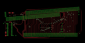
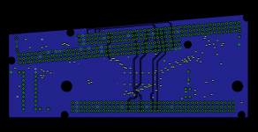
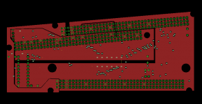
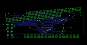
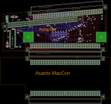
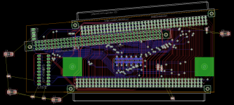
Spent the last two days laying tracks:
Dual Slot MacCon.png

I was able to do most of it on two layers. Only very few connections had to be routed in one of the inner layers. It's all 6/6 spacing, so having the board fabbed should be relatively cheap.

There are big ground and 5V planes in the two inner layers wherever possible. It will have 6 big SMD solder pads to jumper in 0 Ohms resistors for jumping PDS slot power to the Cache slot. Without the jumpers the external floppy power connector is used to power the Cache slot.

PDS passthrough will always be powered by the host PDS slot.


Trash80toHP_Mini

NIGHT STALKER
Beautiful. The holes in the Power and ground planes appear to be clearance for the mounting points? If so, do you have room to break ground out to the surface layers to meet Apple's spec for chassis ground?

Thinking about it, could you add a ground plane representation for your wrong angle adapted NIC for illustrative purposes? That would make direct comparisons to Apple's max card spec and the DiiMO/Artmix form factor clear to all. Love the connector outlines. Showing the interface of the adaoter card/NIC junction would be way cool! Nice work. :approve:

/monthly_06_2017/post-902-0-14811100-1496290826.jpg">View attachment 12983


Bolle

Well-known member
Good idea.

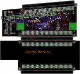
Here it is:

MacCon+Adapter.png

You have the exact specs for mounting hole positions at hand? I used what I measured on my machine using the papercraft technique :p - Edit: found it.

Seems like I have to move around the chassis mounting holes a bit. Maybe my chassis is bent a little.

Also do you happen to have the measures of the Artmix card? - Yet another edit: extrapolated it from a picture. Artmix card should have a height of around 12,8cm measured at the topmost right corner. This matches exactly the size of the stack of MacCon and my adapter.

There is enough space around the mounting holes on mine that I can break out ground to the screw surroundings. Will do that.

 
Last edited by a moderator:

Trash80toHP_Mini

NIGHT STALKER
Very nice! If you could add a 1cm w x 10 cm h white box next to the new graphic for easy scaling, I can print it out on the laser printer at work to test fit in my /30. I've pasted up artwork for adding a second PDS passthru  parallel to and underneath the IIci slot and a smidgeon farther forward than your vertical PS slot. But the emailed FAX file didn't come through from work for me to post right now.

You've probably got beaucoups headspace for your GS card as compared to the klugestack in the gamba series. Try shoving the IIci/vertical slots as far up as clearances allow and the lower passthru will probably sit nicely above a low profile 2.5" SCA server drive, SCSI2SD or equiv. without interfering with the mounting points.

The rear chassis ground pad is a small circle, BTW. Oonly the front pad is a big rectangle. [;)] ]'>


joethezombie

Well-known member
Wow.  Just wow.  That is nothing less than a work of art!  Absolutely beautiful!  

I hope you do not find any major errors :p

Spent the last two days laying tracks:
Ha!  Well I did go over it once before and didn't find any errors.  But I really want to make sure everything is perfect.  I would be devastated if a batch of boards were ruined because of a mistake I made!


Trash80toHP_Mini

NIGHT STALKER
That would be awesome, thanks for the suggestion. It would need to be on the solder side of the board.

View attachment 14484

Lopping off the rear mounting hole extension of the add'l PTSlot connector moves it much closer to the circular chassis grounding point in Apple's spec. bringing the thruholes well awayof the front edge of the your board. It looks like there's plenty of room on component and solder sides to route traces through TTL driver ICs if necessayy.

BolleBoard.jpg

 
Last edited by a moderator:

joethezombie

Well-known member
Currently checking the connections again. So far I have found a couple of anomalies on the CACHE connector.  Pins B23 and C20 are listed as n.c. in DCaDftMF, but they are connected to GND on this card.  Pins C7 and C17, also listed as n.c. on the CACHE slot, are indeed n.c.


joethezombie

Well-known member
I am nearly completed with the verification process.  Everything is checking out perfectly other than the GND connections detailed previously, but I do still have 30 or so signals to go.  I do want to point out one concern.

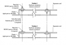
If we look at how expansion cards are mounted to the chassis, we see this:

se30-mount.png

Notice how the bracket towards the front of the SE/30 secures on the component side of the card, and the bracket to the rear of the SE/30 secures to the solder side.  If we look at Bolle's amazing design, it appears as traces in those areas are going to be in contact where vibration or excessive tightening could compromise the connections.  I bring this up, because I have card that was mounted incorrectly (the installer put the mounting bracket on the wrong side) and over time, it has rubbed off the traces.

I also have another card that has thick transparent stickers covering traces in the bracket contact area.  If the traces can't be moved easily, that may be a good solution.

Anyway, required mental diversion completed, back to verifying!


Trash80toHP_Mini

NIGHT STALKER
I'm all but certain that the much smaller, circular chassis grounding provision spec'd for the rear mounting ear was to act as a structural "washer" preventing compression damage to the board. Only the one point at the front was really necessary for grounding purposes.

Also note that automotive type (plastic) snap rivets are specified, not machine screws interfacing with tapped holes. Compression of the board from an over torqued connector would also be prevented in that manner.


Bolle

Well-known member
I tried to leave space. Traces can however still be moved a bit more out of the way. Then again I was going to add electrical tape anyways.

Also the big ground ring/pad should not be flat and provide further distance between card and bracket.

I moved stuff around a bit anyways as I tried to implement a small power supply using LM2576 to derive the extra 5V for the Cache slot from the 12V feed of the power connector.

I am not yet sure if I will implement this. Maybe it will be optional and can be bypassed by another jumper.

 
Last edited by a moderator:

joethezombie

Well-known member
All of my SE/30s have come with machine screws and nuts holding the expansion card, or no fasteners at all.  I think I'm going to use nylon screws and nuts in my final project when it's time for permanent installation.

Back on the verification front, I am now reasonably satisfied that my schematic is correct and complete.  By now, I've checked everything at least four times.

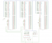
Here's the final, showing the grounded n.c. connections (I removed the 2nd PDS slot in this version for brevity):

dualport.5.png


Bolle

Well-known member
So if I get things right those two pins on the cache connector should be n.c. according to the slot pinout but are grounded on your adapter?

Should we have jumpers so we can choose to either ground them or leave them open just in case? At least on the first batch of board

 
Last edited by a moderator:

joethezombie

Well-known member
Correct.  I think Artmix also ran into a similar dilemma .  I see on his adapter, CACHE pin C7 (which is also listed as n.c.) is ran to JP1.   That jumper is open, but if it were jumpered, it would connect C7 to GND.

Perhaps it would be a good idea to have jumpers on these n.c. pins.


Bolle

Well-known member
Ha! Gotcha. So back to laying traces.

Figured the jumpers on the Artmix card had to do exactly this.

 
Last edited by a moderator:

joethezombie

Well-known member
Hmmm...

So I can't seem to get a Pivot IIsi working off the THRU port.  I have my wrong-angle adapted Asante, followed by the DualPort with the PowerCache.  This works well.  But when I plug in a Pivot IIsi on the passthrough connector, I get a black screen on the internal monitor.  I haven't built up a connector for the pivot, so I am unsure if there is video-out present.   More testing to follow...

An interesting observation, the C40M signal (pin B1) is not connected through on the Asante cards (both of mine).  I can find no references describing this signal anywhere.

 
Top