• Updated 2023-07-12: Hello, Guest! Welcome back, and be sure to check out this follow-up post about our outage a week or so ago.

ProtoCache1 - IIsi/SE/30 PowerCache Adapter Prototype Development

Trash80toHP_Mini

NIGHT STALKER
As a group, we've collected a lot of information in the last iteration of this impossible dream:

IIsi PowerCache TwinSlot Adapter - Cloning Project

Now it's time to finally move from the theoretical to the practical  .  .  .  in wire wrap. For those of you who weren't born in the dark ages, wire wrapping was used to prototype the Apple1 through the Macintosh as well as the IBM PC. It was probably used to prototype everything else back to the dawn of the Dual Inline Package IC age of electronics as well.

www.nutsvolts.com - wire_wrap_is_alive_and_well

SJ wrapped boards for the Woz. Burrell Smith wrapped the first Macintosh Prototype as part of the Mac Development Team. Don't have any pics of those, so here's what the first IBM PCs looked like:
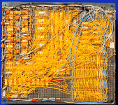
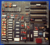
_IBMMBB-wire wrap.GIF_IBMMBF-component side.GIF

Sweet, found pics of Mac prototypes in folklore's PC Board Esthetics and Macintosh Prototypes articles:

wire-wrap.jpg.61411be87dc868ac2b953ca384fceb9d.jpg


wirewrap83a.jpg.71fa46307ee0dc1f371248a2435dbba2.jpg


This is what ProtoCache1 looks like during test fitting of the first 120 pin RA Male EuroDIN connector for the '030 PDS I spliced together from parts of two 96 pin "NuBus" connectors:

/monthly_05_2017/post-902-0-76475600-1495680303.jpg">View attachment 12863

It's not much, but it's a start. TimHD got in touch with me to see if pics of this passive Mobius adapter would be useful. Absolutely! Based upon that design I started plans to build ProtoCache1 in a gated configuration to act as passive IIci slot adapter or in active adapter mode with the flip of a DIP switch when I have new PALs to test in the sockets. Hopefully the one I have at hand will work, we'll see.
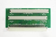
Mobius_040_Card-IIsi_Adapter-1.jpg

Samurai-j hooked me up with these pics of his Sonnet IIsi Adapter today. It's another passive card and I think I should be able to figure out the few connections that aren't plain as day on the three layers of this almost transparent card.

up162583.jpg


up162584.jpg


We'll see what happens, I'm already working in Illustrator to reverse engineer the other card TimHD has obtained. It's a single DIP PAL model, probably a fraternal twin of the PAL on the TwinSpark adapter. Omidomo will be helping out by buzzing connections on his TwinSpark,m so between these four examples and a pair of adapters that I have here, I think we're in pretty good shape. Time will tell. 

I'm hoping that the prototype in passive mode will function correctly in my SE/30 with its Video ROM removed, disabling Video and hopefully removing memory conflicts with my 50MHz PowerCache. A Radius Color Pivot II IIsi will be installed in the PDS passthru. We'll see. [:)] ]'>


Trash80toHP_Mini

NIGHT STALKER
OOPS! Make that four layers of traces and a lot more guesswork to do on that Sonnet adapter. samauri-j, have you got a pic of your Sonnet 040 to post, it doesn't need to be high resolution. The Mobius 040 looks like it may do the active conversion with the PAL located at U7, so I'm sondering if your Sonnet 040 card might be doing the same kind of thing?

Mobius_040_Card-1.jpg


Themk

Well-known member
Awesome put together! I'm familiar with wire wrap, and I can't wait to see what your project looks like after its been done being wrapped.

I could design a PCB based on physical dimensions, and a/the schematic. This would allow it to become more than just a wire-wrapped prototype, for distribution to other people. We could provide the Gerber files, allowing people to order and then solder/assemble their own PCBs.

 
Last edited by a moderator:

Trash80toHP_Mini

NIGHT STALKER
Thanks, it took longer than I imagined to put the IP together. My board won't be as tidy (if you can call them that) as the PC board and probably messier looking than the Mac board. They didn't have to worry about trace lengths, but at 16MHz for the SE/30 and 20-25MHz for the IIsi, my trace meandering will be loopy arcs of wires. It might turn out lookin' kinda cool that way now that I think about it. ;D

It'd be a big help if you could get some numbers together on producing a four layer board (six with power and ground?) to see what costs will be. It'll wind up at least the size of the TwinSpark for the SE/30, the IIsi version would be about half that size. CoPro will have to be on a card in the passthru. Learning to design for modern production isn't really on my to do list. I'll be happy slaying this windmill if I can or even just giving it a good fight.

There are three (or four with a pair of passthru connectors) $10+- Connectors involved, so it's not going to be a "cheap" adapter if we can pull it off. But releasing the spec under an appropriate not for profit license should allow for groups to buy boards, connectors and PALs in good size lots to keep costs at least reasonable.

 
Last edited by a moderator:

Themk

Well-known member
All numbers (unless otherwise stated) are based on 180mm*100mm, 4-layer, 1.6mm thick PCBs. (sorry I think in SI units) Note: This does _NOT_ include the cost of PALs, connectors, assembly, test, etc. It's just for a BARE board::

From SEEED:

10 @ $122.60, 20 @ 165.80, 100 @ 522.90

From elecrow:

20 @ 143.70 (NOTE: based on PCB of 160cm*100cm), (for 200*100cm cost is 169.80)

Ehh, there's probably more. But I'm tired. I just coughed those up easily. 180mm by 100mm figure was taking from measuring my SE case.

EDIT: In addition to the above, I also ran it through PCBShopper (just now actually! Didn't have this ready when I first made this post):

PCBShopper.pdf


Attachments

  • PCBShopper.pdf
    907.3 KB · Views: 490
Last edited by a moderator:

Trash80toHP_Mini

NIGHT STALKER
You must be tired 160cm*100cm makes that a pretty big SE case you're measuring there! [ :D ]

Pricing is a lot better than I was expecting. 10cm high is fine, widthwise it was impossible to use a 10x10cm SEEED type board for even doing a rough blank to wrap most of the connections, 3.9 inches of thruholes just won't fit. My plated perf board is 12cmx18cm, could use the 9cmx15cm board, but I wanted to have more room for fiddling with it, for the passive/active gating, the PAL later on and maybe trying an extra passthru connector on for size.

I'm wondering if 100mm is really tall enough if we go with the DiiMO/Artmix form factor? Likely not if we throw a second PDS passthru on it?

edit: this is getting WAAAAY too far ahead of things. I'm glad to know it won't cost a fortune if it proves possible to make it work though!

 
Last edited by a moderator:

Themk

Well-known member
180mm was sticking up from bottom (touching LoBo in my measurements) to top of PCB. I got a little generous with width requirements, that's okay. Everything that makes it smaller makes it cheaper. At least now we know the high(er) side of the price equation.

Yes, my thoughts too. Let's just focus one thing at a time.

You already have a PCB designer [;)] ]'> to finalize your design, and you have motivation that PCBs aren't going to be breaking the bank either.

Keep it coming!

 
Last edited by a moderator:

samurai-j

Active member
OOPS! Make that four layers of traces and a lot more guesswork to do on that Sonnet adapter. samauri-j, have you got a pic of your Sonnet 040 to post, it doesn't need to be high resolution. The Mobius 040 looks like it may do the active conversion with the PAL located at U7, so I'm sondering if your Sonnet 040 card might be doing the same kind of thing?

attachicon.gif
Mobius_040_Card-1.jpg
I have disposed IIsi.

Therefore, the Sonnet adapter has never been used.
The photo product is Tokamac IIci 33 Mhz version of the same product as Sonnet Presto 040.
Tokamac IIci 33 Mhz also works with Presto 040 driver software.
 
You are really active and nice geek
 
up162586.jpg


Trash80toHP_Mini

NIGHT STALKER
Thank you! Though I think of myself as an artist, geek will do.  [:)] ]'>  There are a lot of PALs on there that could be doing the adaptation. Very nice boards!

One request for help as I turn in for the night, gang. I could use recommendations on an IC for A/B switching the board from straight thru passive mode to running the appropriate signals through the PAL adaptation.

An IC that's at rest in one mode and switches on a high signal to the other would make things easy for me. It needs to be available in DIP for the wire wrap sockets. That way I can use soldertail sockets as little breadboards in the wrap sockets as substitutes until I'm ready to finalize the active component circuitry and then install the real deal in the wire wrap sockets..


Trash80toHP_Mini

NIGHT STALKER
LOL! I'm hoping someone will do that leg work for me  .  .  .  maybe even design the generic A/B bus switching circuit too. Digital circuit design's not one of the areas I've explored and I've got my hands and noggin full with plenty of other stuff ATM. :scrambled:

Working out a pinout table for the three connectors involved from various partial efforts in different board layout files is something I should have done a long time ago. I've worked backwards from the PAL/GAL pads to see where they led on the PDS and looked up the signals on a piecemeal basis. Now I need to work out the full control line pinout as well as the address/data bus configurations for wire wrapping the basics. I've got eight wire colors available for coding the different functions in the wrap. That should make troubleshooting and active adapter circuit development much easier.

DiiMO-WIP-Signals-Pinout-01.PDF


Attachments

  • DiiMO-WIP-Signals-Pinout-01.PDF
    208.1 KB · Views: 127

Themk

Well-known member
LOL! I'm hoping someone will do that leg work for me  .  .  .  maybe even design the generic A/B bus switching circuit too. Digital circuit design's not one of the areas I've explored and I've got my hands and noggin full with plenty of other stuff ATM. :scrambled:
Should I be taking that as a nudge? I could do that. You will have to let me know everything that has to be switched. :simasimac:

That being said, if you can do everything else, I think you can probably cough up the digital switching circuit. I can go dig out some IC part numbers to go hunting for.

 
Last edited by a moderator:

Trash80toHP_Mini

NIGHT STALKER
As I've said before, this is a communal open source (not for profit licensing) development project, NOT MY HACK! [:D] ]'>

I've long realized that I shouldn't be struggling to learn everything there is to know. I know what I know and more importantly, I know what I don't know. If I don't need to know it, why learn it unless it's interesting? I've stuck to what I've liked of what needed to be done and partnered or hired help do do what I didn't want to do or didn't enjoy doing, especially repetitive stuff I've figured out an easy way for help to do. This worked well in my business and in the font emulator project that was related to my chosen field. It's worked well on a couple of other projects here in the past, why change now?

I was going to PM a couple of folks with vast experience in this area, but thought I'd just chuck a plea for help out into the open. I've got no desire whatsoever to make like I can do everything required. [;)] ]'>


Themk

Well-known member
Yes that makes sense. When you say "NOT MY HACK", you need to give yourself more credit, you are wire wrapping the first prototype!

Your philosophy makes sense, and I am happy to cough up a digital switching circuit. I was merely trying to suggest that if you could prototype the adaptor, you could probably use the same skills to prototype a digital switching circuit.

I can look more at designing the PAL/GAL/CPLD/whatever, I might be able to help in that field too, we will have to see. ATM, I'm signed up for building and designing the PCBs.

I'll go dig out some of my favorite mux IC part numbers.

BTW: Trash said some things about this project in this thread.

 
Last edited by a moderator:

Trash80toHP_Mini

NIGHT STALKER
*** HEH, get in a plug! If anyone knows anything about how Bus Mastering works in the Slot Manager NuBus or PDS, gimme a shout. If you just remember which volume of Inside Macintosh I can find that informetion it would be a big help. That appears to be the IIsi Nubus Adapter in SE/30 "impossible dream" bottleneck. I really miss having bbraun active in the hobby. :-/
That's the most useful thing I think i said in that thread  .  .  .  really! If anyone knows where I can find that info in Inside Macintosh, I'm up for taking a shot at figuring Bus Mastering out. At least as regards the SE/30 PDS' aversion to dealing with Bus Mastering Cards, now that's my kinda crazy dream!

Digital logic tinker toy sets have never done it for me, my partner in crime took care of that and the programming. Programming didn't do it for me either, though I was pretty good at it when I figured out I didn't like doing it way back in the day.


Themk

Well-known member
Programming and I have mixed feelings. I'm starting to realize that I'm more a EE person, not a CS person. Of course, Music is my real gift.

That being said, I am not a disaster when it comes to programming. I just simply have mixed feelings with it. That's all. I still enjoy programming, but, that depends on which cycle of the mixed feelings I am on [:p] ]'>

I guess that could be said about a lot of things, it comes in cycles. Programming is fine, Electrical Engineering is fine too, but it comes in cycles.

 
Last edited by a moderator:

Trash80toHP_Mini

NIGHT STALKER
AHA! Thanks for running those numbers for me, you gave me a new idea! Could you price out something on the order of a 12cmx12cm two layer board for me?

I'm thinking along the lines of ordering a batch of prototyping boards using soldertail sockets for the IIci slot and a pair of PSD passthru slots that would already be wired together at the trace level. I'd be using etched breakouts for soldering sets of wire wrap headers for the connectors. That would make the mobo plug the only wire wrap socket on the board!

All power/ground/housekeeping lines would be implemented on the board. That would increase reliability, reduce cost of connectors and make rewiring corrections much easier along with having multiple variations possible. The balance of the board would be prototyping area just in case. The A/B switching circuit would be done in etched copper traces and I'd put SMT pads on the design for socketing the PAL I have on the IIx adapter. All the signal IDs could be etched in the copper as well. No need for a silk screen layer if that might reduce cost.

Sounds like win, win, win all around for a not so terrible investment, whatcha think?

Anybody else got any ideas to chime in with, it's too quiet in here.
 

Trash80toHP_Mini

NIGHT STALKER
Maybe someone who's really good at soldering (I'm definitely not good at it at all [:I] ]'> ) could volunteer to do assembly. That would be a major contribution to the project, especially in terms of prototype board reliability when I'm wrapping the balance of the connections.

 
Last edited by a moderator:
Top