-
Updated 2023-07-12: Hello, Guest! Welcome back, and be sure to check out this follow-up post about our outage a week or so ago.
You are using an out of date browser. It may not display this or other websites correctly.
You should upgrade or use an alternative browser.
You should upgrade or use an alternative browser.
ProtoCache1 - IIsi/SE/30 PowerCache Adapter Prototype Development
- Thread starter Trash80toHP_Mini
- Start date
For JT:
Prices are for 120mmx120mm, 1.6mm thick, 2-layer PCBs.
From SEEED:
10 @ 38.80.
Now, here is the tricky part: If you can manage to cram everything into 100x100mm, then the price goes down to $4.90 for 10 boards! As to why increasing the per-board size by 4cm^2 sends the price up exponentially, I dunno.
From other manufacturers (I took a trip to PCBShopper):
PCBShopper-2layer.pdf
Attachments
Last edited by a moderator:
Trash80toHP_Mini
NIGHT STALKER
Nope, 12cm wide is the minimum for a PDS connector. The 40x3 grid is 3.9" wide. I'll be roughing out the requirements in Illustrator, looks like a plan!
Trash80toHP_Mini
NIGHT STALKER
Their production process/tooling setup is optimized for 10cmx10cm and smaller PCBs for the Arduino/Raspberry Pi community. They're likely basing their boards by multiples of that $4.90 baseline. Doubling the dimensions quadruples the area and likely puts final production on a different setup with lower volumes for designs that cross the design limit boundaries of 10cm x10cm blanks. Such also puts handling/packaging for shipment into the custom category. I always figured a PDS card would double and quadruple prices for IIsi and SE.30 respectively. Additional charges on top of that are understandable.From SEEED:
10 @ 38.80.
Now, here is the tricky part: If you can manage to cram everything into 100x100mm, then the price goes down to $4.90 for 10 boards! As to why increasing the per-board size by 4cm^2 sends the price up exponentially, I dunno.
I wouldn't be surprise if we could more closely approach a 20cmx20cm board size without doubling cost. additional height would be most useful and a bit of width would put us into the DiiMO (or Artmix' Clone thereof) form factor range from side to side. I certainly don't require its clearances for the drive cage assembly. :rambo:
That $21.64 to $330.00 variance in the quotes did surprise me a bit. Tighter tolerances/better quality not required. [
I've changed my thinking a bit about using a wire wrap connector for the PDS slot. Using a soldertail connector and moving the wire wrap header connections for it above the chassis deck opens up some interesting configuration possibilities for in terms of heavily modifying my empty Classic case/chassis for the prototyping setup. Sourcing a parted out chassis/bucket from one of the gang here with a dead SE/30 or SE with the late model chassis for modification would be optimal.
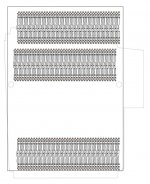
p.s. check out the .PDF in this post for an idea of what I was thinking of etching and drilling when I thought prices would be prohibitive for SEEEDing a set of ProtoBoards. Substitute standard parts for the wire wrap parts. I was testing a simple trace length equalization in Illustrator.
Last edited by a moderator:
Trash80toHP_Mini
NIGHT STALKER
Trash80toHP_Mini
NIGHT STALKER
Attachments
Okay, well, I knew all about the whole 10cm*10cm being the whole ya know you explained it well. I just didn't expect the price to go up THAT much. Looking at it though, it looks like the 'normal' price for 10cm*10cm on SEEED is $10, so not as dramatic, but it appears to be permanently(?) discounted to 4.90.
Great graphics too, THX!
The smaller the PCB the better. Thank goodness IIsi forces us to scale it down. At the same time though, we have to be mindful of the drive bays in the SE/30, which puts us at making a taller (and much more expensive PCB). I can already hear folks complaining that "WHY IS THE SE/30 VERSION MUCH MORE EXPENSIVE THAN IISI!" :
That being said, it must be wide and tall enough to work well.
Also, no CoPro socket for IIsi, we hope you have one on your accelerator
Also regarding quality, noticed I selected some sort of quality certifications in my PCB compare search. It's not much, but it is something.
P.S. I'm going to need a IIsi for this, to test all these boards in.
Last edited by a moderator:
Trash80toHP_Mini
NIGHT STALKER
cart-horse [ ] ]'>
] ]'>
There is a VERY long road ahead before anyone will be testing anything outside the ProtoCache1 phase. I've gotta get feedback from all the players to refine the pinouts of their boards and I have to reverse engineer my two boards. That all has to be analyzed before we even start thinking about implementing, much less trying active conversion. I'd sort of like to keep the magic smoke contained inside my 50MHz 030 PowerCache card.
We're not even thinking about final design yet, though the SE/30 card will wind up looking at least something like the DiiMO card. After successful testing with the prototype, I'll be pushing really hard to fit a pair of passthru slots on the production version for the SE/30. Replacing the HDD/cage assembly with a 2.5" HDD or SCSI2SD mounted to the top deck of the FDD cage would almost certainly be a requirement for using a second PDS slot passthru. If someone wants to keep the HDD/cage stock, they could leave the connector below the IIci Accelerator Slot unimplemented.
edit: let me clarify that. The setup on the proposed prototyping blank has the pair of PDS Passthru slots tied together at the top of the card, connected to one set of wire wrap pins. Shoehorning that second passthru/PDS card horizontally below the PowerCache slot will probably be the only way to go. Haven't really studied that cart yet. [ ] ]'>
] ]'>
There is a VERY long road ahead before anyone will be testing anything outside the ProtoCache1 phase. I've gotta get feedback from all the players to refine the pinouts of their boards and I have to reverse engineer my two boards. That all has to be analyzed before we even start thinking about implementing, much less trying active conversion. I'd sort of like to keep the magic smoke contained inside my 50MHz 030 PowerCache card.
We're not even thinking about final design yet, though the SE/30 card will wind up looking at least something like the DiiMO card. After successful testing with the prototype, I'll be pushing really hard to fit a pair of passthru slots on the production version for the SE/30. Replacing the HDD/cage assembly with a 2.5" HDD or SCSI2SD mounted to the top deck of the FDD cage would almost certainly be a requirement for using a second PDS slot passthru. If someone wants to keep the HDD/cage stock, they could leave the connector below the IIci Accelerator Slot unimplemented.
edit: let me clarify that. The setup on the proposed prototyping blank has the pair of PDS Passthru slots tied together at the top of the card, connected to one set of wire wrap pins. Shoehorning that second passthru/PDS card horizontally below the PowerCache slot will probably be the only way to go. Haven't really studied that cart yet. [
Last edited by a moderator:
Yup. I would love to put a 2nd PDS pass through too. Unimplemented for some people, or implemented for others. All boards will have the holes though for economies of scale (and for upgrading later if desired). I don't know if there is any sort of PAL work required to build a 2nd PDS slot, or if it's just straight-through. I'll take your word though.
Um, well, it's possible to put it above the cache slot, and above the first PDS slot. It's all about how giant we want the card to be... I agree though, we should put it below the accelerator/cache slot, and then if people want it they can hack their drive bays. Lots of people already have SCSI2SD, so it shouldn't be a big issue.Shoehorning that second passthru/PDS card horizontally below the PowerCache slot will probably be the only way to go. Haven't really studied that cart yet. [] ]'>
Trash80toHP_Mini
NIGHT STALKER
I don't know what's possible or not, those are just thoughts off the top of my head, we'll cross that bridge if we ever get to it. Right now I'm trying to get the pinouts correct for MB and CI Connectors and everything together into one full size scale reference drawing. After that's done, it's easy enough to swap rows A & C for the PDS passthru connectors.
MB<->PDS<->PDS is a simple bus if no CI slot is involved, no components at all unless we might need some kind of termination. But I'm setting it up so that the CI connection is wire wrapped in series as it is on all the adapters. Connections get shuffled around from MB to CI and then get shuffled back around from CI to PDS_PDS. That way I can test the lashup using one of my several RCPII/IIsi cards before installing the PowerCache card. If the passthru won't run the cheap VidCard I'll know something is wrong. If everything is working the way I'm hoping it will in passive mode, then we start implementing the active mode. Anytime the VidCard stops working on a pre-test of active mode. Switch back to passive to make sure nothing is borked there and then bug hunt the active setup.
Passive setup will look kinda like this:
MB___|||------|||___CI___|||------|||___PDS___PDS
Underscores are traces between connector and headers. Headers = ||| and Wrap Wires = -----------
Last edited by a moderator:
Really quick cheap dirty 3D mockup that took me only 3 minutes to make:
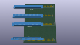
I used 96-pin euro-dins as that was what was available in the library right off the top of my head. It gets the point across though. Also, the 3D footprint looks slightly shifted, but don't worry, it won't affect the quality of the PCBs when done. Also, I will fix that error before I do a production design. As I said earlier, I spent more time writing this post then actually making the 3D mockup.

I used 96-pin euro-dins as that was what was available in the library right off the top of my head. It gets the point across though. Also, the 3D footprint looks slightly shifted, but don't worry, it won't affect the quality of the PCBs when done. Also, I will fix that error before I do a production design. As I said earlier, I spent more time writing this post then actually making the 3D mockup.
Last edited by a moderator:
Trash80toHP_Mini
NIGHT STALKER
Never mind the final design mockup, Cart-Horse! Swap the two center connectors so the PDS slots are on top and the IIci slot is in between MB and the paired PDS passthru slots the way it will be for the protoboard. 
I've made some good progress today on roughing in the IIci slot and its I/O header setup headers. Power and ground buses will be heavier wires soldered into vias. There won't be any wire wrap pins for Power/Ground/Reserved/n.c. to make it easier to keep straight when wrapping the rest of the connections.
I've made some good progress today on roughing in the IIci slot and its I/O header setup headers. Power and ground buses will be heavier wires soldered into vias. There won't be any wire wrap pins for Power/Ground/Reserved/n.c. to make it easier to keep straight when wrapping the rest of the connections.
Last edited by a moderator:
Trash80toHP_Mini
NIGHT STALKER
Who me?  Nah, I just like to kid you about being a bit overeager when it comes to this project. It's only been in the works something like five years and running now.
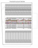
Pretty sure I'll be switching my mode to Keep It Simple, Stupid! Only one PDS Passthru on the ProtoBoard is necessary for my tests, so that's what it'll have. I've got the IIci Cache slot worked out. The heavy dark Red and Green lines are heavier gauge wire Power & Ground buses. PDS will be a lot easier.
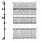
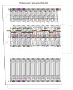
Lots of pretty colors when I "select all" across so many layers in IIllustrator. [ ] ]'>
] ]'>
HiRes .PDF peek: ProtoCache1-pinout-C-000.PDF

Pretty sure I'll be switching my mode to Keep It Simple, Stupid! Only one PDS Passthru on the ProtoBoard is necessary for my tests, so that's what it'll have. I've got the IIci Cache slot worked out. The heavy dark Red and Green lines are heavier gauge wire Power & Ground buses. PDS will be a lot easier.
Lots of pretty colors when I "select all" across so many layers in IIllustrator. [
HiRes .PDF peek: ProtoCache1-pinout-C-000.PDF
Attachments
Yeah, I get over zealous sometimes.
Nice PDF. I love vector graphics because I can zoom in on-screen and everything is still legible, rather than an unintelligent pixelated mess.
For the final product, however, I'll need the pinout schematic in a form that makes drawing it in KiCad easy. Tracing the wires with my eyes to read it works, but a nice layout table would be somewhat helpful. I'll be doing plenty of my own pushing-and-shoving on this later :wink.
Last edited by a moderator:
Trash80toHP_Mini
NIGHT STALKER
Attachments
Trash80toHP_Mini
NIGHT STALKER
How about laying out just six connections for the baseline bus parts.
Modify six copies with legs connecting them to Power and Ground Rails
Stretch three of them to raise the wire wrap headers for the Mobo Connector above the deck.
Modify two of them with antennas connecting them to Power and Ground Rails.
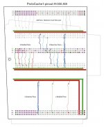
How's that for simple? ProtoCache1-pinout-H-000.PDF
Modify six copies with legs connecting them to Power and Ground Rails
Stretch three of them to raise the wire wrap headers for the Mobo Connector above the deck.
Modify two of them with antennas connecting them to Power and Ground Rails.

How's that for simple? ProtoCache1-pinout-H-000.PDF
Attachments
Trash80toHP_Mini
NIGHT STALKER
We can scratch the two antenna variations for individual power and ground connections from MB to its wire wrap headers. It got late and adding the "antennas" was the last thing I did. I forgot all about ground loop turning them into real antennas!
I'm hoping autorouting will tighten up the distances between the connectors and headers. That eats up a lot of real estate, leaving little room for my switching circuitry I don't want to add another Centimeter to the height if at all possible. Hopefully I can drop the MB wire wrap headers a bit, I did a generous guesstimate.
Physical layout is a bit better, the IIci connector no longer interferes with the front mounting tab. the rear tab disappears with the chassis sections that need to be removed for the estbed bucket/chassis mods. I added a centimeter to the width of the board for elbow room. It's necessary to prevent the connectors from overhanging the edge of the ProtoBoard. It also gives me room to clear the mounting tab with the Cache Slot connector and for routing the Power buses. It's edging closer to the DiiMO adapter's form factor.
16cm high x 13cm wide is looking like a hard number for another spread of price quotes.
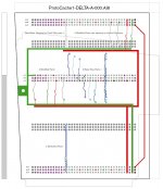
Trace modification count is way down. We're looking at the original basic stretching of three connections and adding P&G drop legs to just four connections. I'll see if I can trim any more fat from the spec in downtime at work tonight.
ProtoCache1-DELTA-A-000.PDF
I'm hoping autorouting will tighten up the distances between the connectors and headers. That eats up a lot of real estate, leaving little room for my switching circuitry I don't want to add another Centimeter to the height if at all possible. Hopefully I can drop the MB wire wrap headers a bit, I did a generous guesstimate.
Physical layout is a bit better, the IIci connector no longer interferes with the front mounting tab. the rear tab disappears with the chassis sections that need to be removed for the estbed bucket/chassis mods. I added a centimeter to the width of the board for elbow room. It's necessary to prevent the connectors from overhanging the edge of the ProtoBoard. It also gives me room to clear the mounting tab with the Cache Slot connector and for routing the Power buses. It's edging closer to the DiiMO adapter's form factor.
16cm high x 13cm wide is looking like a hard number for another spread of price quotes.

Trace modification count is way down. We're looking at the original basic stretching of three connections and adding P&G drop legs to just four connections. I'll see if I can trim any more fat from the spec in downtime at work tonight.
ProtoCache1-DELTA-A-000.PDF
Attachments
Last edited by a moderator:
Trash80toHP_Mini
NIGHT STALKER
Spent most of my lunch hour folding, spindling and mutilating a printout and it looks like I can drop the headers for the MB connector at least a half an inch! ;D
Similar threads
- Replies
- 70
- Views
- 5K
- Replies
- 67
- Views
- 4K
- Replies
- 25
- Views
- 3K
- Replies
- 9
- Views
- 2K
- Replies
- 0
- Views
- 738

