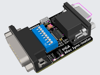
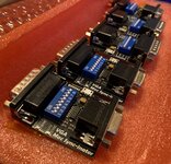
The hardware is beginning to take shape in my mind, in a way I'm pretty happy with.
After more tinkering I discovered that the adapter keeps functioning when the phantom-powered voltage is as low as 2.75V, and maybe it can go even lower. So I feel comfortable with the idea that the microcontroller will always be on, with no way to turn it off. I'll include a USB micro port on the adapter for optional external power, just in case there's some situation where it's needed, but I expect it won't be necessary.
I've also massaged the code for sync splitting to where it's working pretty reliably on my IIci with the two monitors that don't normally work with the IIci. It's entirely a mcu program for sync processing, with no other active components needed. The sync splitting code also works well with two other monitors, even though it wasn't needed on those monitors because they also support composite sync. But it causes trouble on another monitor that works fine with composite sync, meaning that sync splitting actually makes things worse for that monitor. So I'll definitely need to include an optional way to put the mcu into "bypass" mode, where the existing sync signals are just passed through without any fancy processing, for cases where the processing causes trouble.
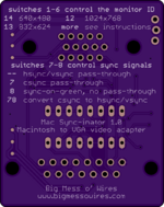
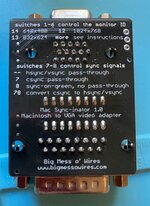
I can use two DIP switches with four permutations to configure the mcu into one of four sync modes: hsync/vsync pass-through, csync pass-through, sync-on-green (no other sync is passed through), and mcu-assisted splitting of csync into hsync and vsync. That should cover all the cases that regular VGA adapters can handle, and with an optional sync splitting mode too, with just two DIP switches.
The full gamut of monitor ID sense codes needs six DIP switches when implemented in the typical way. So this adapter could have 6+2 = 8 total DIP switches. I might be able to do something clever and reduce the number of DIP switches needed for the sense codes by 1 or 2, by eliminating support for rarely-used sense code IDs. But I'm not sure it's worth it, since there's not much practical difference between an adapter with 6, 7, or 8 DIP switches. You're still going to need to refer to a chart to remember what all the switches do. I'd hoped to avoid that but I don't think it's really plausible.
My initial attempt at phantom powering had Schottky diodes connected between each sync signal and a 47 uF capacitor on the mcu's supply pin. That worked fine, but I later discovered that I don't even need those diodes. If the sync signals are connected to mcu input pins, then the mcu will magically turn on when sync signals are applied even if the mcu supply pin is completely disconnected. The sync signals will pass through the ESD protection diodes in the input buffers and inject current into VDD. This is a cool party trick, and would eliminate the need for some external components. But external diodes are probably safer, and Schottky diodes also have a smaller voltage drop than the silicon diodes used for ESD, so the resulting phantom supply voltage would be slightly higher if using external Schottky diodes.
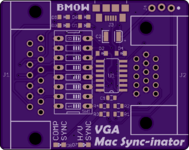
My hardware sketch looks something like this: An ATTINY204 microcontroller (14 pins, 11 usuable I/Os) is the only active element. The Mac's csync, hsync, and vsync signals are each connected to a Schottky diode which feeds a large-ish bulk supply capacitor, something in the 10s of microfarads range. That's the phantom power supply. There's also a USB-B micro connector for external power in case of emergencies, and a microcontroller programming header (or footprint for one).
The Mac's csync, hsync, and vsync are connected to microcontroller inputs, and the VGA hsync and vsync are connected to microcontroller outputs. The code can connect sync inputs to sync outputs in one of four different ways, specified by two DIP switches. Six other DIP switches set the monitor sense ID, but aren't connected to the microcontroller. There are 8 total switches.
There are two LEDs that light up to indicate when a composite sync signal is present, and when separate hsync/vsync signals are present, for quick troubleshooting.
That's 8 or 9 I/O pins depending on how the LEDs are handled, which leaves a few extras for something else or they can be left unused.
I believe that an adapter like this could do everything that other Mac-to-VGA adapters do, so you'd never be worse off by having it, and it would also have the bonus feature of sync splitting for the IIci, IIsi, Toby, and others that can benefit from it. I'll make the sync splitting code as robust as I can, and while I'm sure it won't work in every situation and for every monitor, it will hopefully work for all of the common ones and will be a valuable extra tool in the Mac collector's toolkit.
 It's hard to search for it with Google because the results are polluted with info for modern OSX machines.
