• Updated 2023-07-12: Hello, Guest! Welcome back, and be sure to check out this follow-up post about our outage a week or so ago.

ProtoCache1 - IIsi/SE/30 PowerCache Adapter Prototype Development

Trash80toHP_Mini

NIGHT STALKER
I thought I just said something along those lines?

Open sourcing everything but the GAL (ROM, sorta) under a non-commercial use license would the working assumption. Licensing the design for batch production at a workable profit level ought to make the various adapter configurations available at not cheap, but reasonable cost levels that should be less than rolling your own. But that's all waaaaaay in the future.

Everything about production/open source release licensing is just a waste of time and effort at this point. Let's get the ProtoCache1 Developer Board up and running before jawboning about such shall we? ;D

 
Last edited by a moderator:

joethezombie

Well-known member
With the PAL decode behind us, I want to express my thanks with a HUGE shoutout to Porchy at http://www.jammarcade.net

Their blog is an amazing trip down arcade board repair, PAL decoding, and generally great electronics repair.  Really guys, it's his expertise with CUPL that we now have a working fusemap.  I may have decoded the equations, but without his in-depth knowledge of product terms and condensing these things down to fit the PLD, we'd still be in limbo on the IIsi compatibility.

Next up, board creation.  Since nobody has stepped up for that role, I figured it's time to get my fingers all greasy again.  Here's my first attempt at board creation in KiCad.  LOL.  I don't know what I'm doing.   :lol:

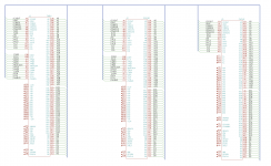
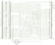
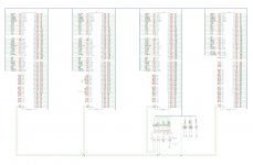
The schematic.  Currently, only the 1:1:1 connections are completed.  Signals with pull-ups, pull-downs, and PAL connections still need to be added.  

dualport.png

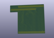
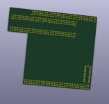
The board.  It's not to any measurements, other than the pin connectors are the correct spacing.  It's more of a proof of concept to see if I could even make a board, but it seems to be working!  The autorouting is a bit rough. I'll probably try my hand with push-shove during the next play-time session.

DualPort.png

 
Last edited by a moderator:

kreats

Well-known member
I think it's totally up to joe what he does with his work.

I've already got a Twinspark I paid heaps for anyway - it'd be nice if everyone had the same opportunity (daystar + ethernet will set you back $150 on their own these days).

 
Last edited by a moderator:

joethezombie

Well-known member
More play-time today, PAL is all wired in!  Next up will be the power connections, pull-up/down resistors, and capacitors.

dualport.2.jpg


joethezombie

Well-known member
Hey all, I just want to come clear with a little information which some of you may not be aware. 

 
Please understand that the work we have completed so far has been a totally collaborative effort, and how we decide to proceed is not just a one man decision.  What you don't see is the hundreds of replies across dozens of PMs, and even on multiple forums, between jt and myself discussing and theorizing on ideas on how to clone this adapter, and how to morph it into a form that fits our needs.  Keep in mind, before this project, I had never touched digital electronics, or programmable logic.  I'm just some lucky schmuk who found a card after years of searching, pulled the chip off, dumped it, and screwed around with a logic analyzer.  The work isn't just mine-- jt has been absolutely instrumental in getting me up to speed, explaining his findings over previous attempts, sharing confirmed pinouts, and more.  And of course I have previously mentioned Porchy before, and there is no denying his contribution was a huge windfall for the IIsi compatibility.
 
Now with that said, I did state that all materials will be open.  And that is true.  All the equations for the PAL, and even the pinout of the card have been posted previously in this thread.  And in the coming weeks, the schematic will continue to be posted when I work on it until completion.  Anyone competent with CUPL could right now create the fusemap with the equations I have provided.  Anyone can see the pinout and create their own board.  Right now.
 
The issue, and we really haven't even decided if it is an issue, is there are some unsavory manufacturers out there.  Case in point, BMoW sells the ROM-inator II, which is based on Doug Brown’s original Mac ROM SIMM design.  He licensed it, and a proceed of the sales goes back to Doug.  But there is a manufacturer using this same design, without permission.  This is wrong.  We kind of want to avoid that same thing happening, so maybe the compiled fusemap should be protected.  I say maybe, because we don't know yet, perhaps we won't even care. 
 
But let me assure you, no one is looking to make money here.  The cards will be sold at pretty much cost, maybe a small fee for time spent.  I don't even know how much that would be, because we haven't priced anything other than "like new" GALs on eBay.  Hell, we don't even know if there is a real demand for these things, other than the dozen or so community members that have posted here.  I joined on doing my part simply because I want one for myself, not because I want to make or *shudder* support a product.
 
So that's all for this morning.  Thanks so much for your interest, and hopefully a solution will be here in the next few months that can make everyone happy and at a very reasonable cost.
 
Last edited by a moderator:

Bolle

Well-known member
I said this already a few times but you can not say 'thank you' too much.

Thanks for the hard and persistent work joethezombie, jt and unknowingly Porchy  ;)

With the schematics now being readable even for me  :?:   I might give it a try to get an adapter board whipped together that stacks on top of a MacCon and has another passthrough.

That way one could easily get two PDS cards + accelerator without wasting so much space as with the TwinSpark form factor.

I did not measure it out exactly yet but that way it might even be possible to do Ethernet+grayscale+universal Powercache all at once.

 
Last edited by a moderator:

joethezombie

Well-known member
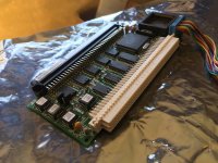
Awesome!  I really envision all sorts of cards to meet individual needs.  We've discussed what you are proposing previously, and that is something I want to see as well.  I have even already modified my ethernet card with the wrong angle hack:

IMG_1434.jpg

And if you are using an SCSI2SD, we can get rid of the HDD cage and make a card with two PDS pass THRUs and a CACHE slot like this (not to any exacting measurements, yet):

triple_slot.jpg

Of course, power requirements for something like that is going to need an ATX type conversion with a supplemental power input on the card.  And with all that space on the bottom of that type of card, we could probably include mounting holes for the SCSI2SD to fit there!  Or maybe even put the extra PDS header down there pointing vertically, and fit the ethernet card there without having to modify it.  So many possibilities!

Maybe even BadGoldEagle's awesome Pivot design!

I would love to see what you come up with, and if you need a GAL, I'll ship one out for free to any card developers.

EDIT:  I just want to point out that the schematics are un-checked and not complete.  I'm sure there exists errors in there somewhere... use at your own risk!

 
Last edited by a moderator:

Trash80toHP_Mini

NIGHT STALKER
YAY! Activity commences! [:)] ]'>

Just messaged this to joe:

Did some measuring already, looks like maximum slottage cubic will be harvested by bolting a vertical mount/sled for the HDD up to the chassis/bezel interface and rear HDD mounting screw on the FDD. slightly contorted bends, but no problem using a sheet metal seamer or even lineman's pliers.

If full reversibility isn't a concern, the half-height 3.5" HDD can be bolted right up to the cover panel of the PSU by drilling four holes. IT FITS!

Looks like there's about 65mm available, which is adequate for the equivalent of THREE NuBus Slots! [:D] ]'>

That may translate into PowerCache, one vertical (even the tall GS Card!) and two horizontal PDS slots, using all three(?) available interrupts on the /30.

Been thinking about the power issue. Using a DC--DC Buck Step Down Converter on the Molex connector's 12v line to power the extra passthru slots seems the way to go about it at this point. No stress at all on the 5V rail of the stock PSU and next to no acreage required to implement the connections on the adapter.

I'm thinking most users would be using the board in its DiiMO config with the extra connectors unimplemented.

Thoughts?
Gotta add that we've still got the line driver issues of the PDS to address. It' spec'd to drive only two TTL inputs. That'd be PowerCache and vertical passthru card in the DiiMO/Artmix form factor. I've got p.112 of the CMOS Cookbook open looking at the 4050 HEX NONINVERTING BUFFER & TTL DRIVER as I'm typing this. Suggestions requested. ISTR using 74LS245s to drive a stupid long cable back in the day. They're tri-state and in the one design example I've found so far it looks like they work both ways at the same time in that parallel port implementation.

Never done the electronics end of digital design, so we need help on this line conditioning conundrum as well as feedback on feasibility of my voltage stepdown approach to spec'd PDS power limitations.

More AI playtime coming up! :ph34r:

 
Last edited by a moderator:

kreats

Well-known member
joethezombie: I like your general ideas, but selling simple memory chips on a SIMM socket should not be something anyone should be upset about or feel that they can protect. They are not selling the programmer.

If you want to support dougg you know where to buy it (I did).. but if you want to buy something cheaper you have that choice too.

 
Last edited by a moderator:

Trash80toHP_Mini

NIGHT STALKER
Ethics and possible concerns are not really a subject for general discussion here, PMs work just fine for that. As joe said, nothing has been looked at very closely yet, much less decided.

Back to development: What's the center to center slot spacing on the TwinSlot type boards for the IIsi?

Nubus Slots appear to be about 24mm center to center, if  20mm or so works, I think we might be in business. If the rear mounting ear is bent out of the way we can probably fit three horizontal cards between the FDD can and the CRT by only using the front mounting point.

That's been my working assumption all along as in the drawings on the second page.

 
Last edited by a moderator:

Bolle

Well-known member
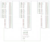
I like to visualize things a bit... why in the world couldn't they go for a more straight through design compared to the 030 PDS for that cache slot?  :lol:

dual slot basic schematic.jpg

Next up I will check this against all the notes we already have in this thread to rule out any errors.


joethezombie

Well-known member
Sweet!  That's absolutely fabulous Bolle!  Great to see that.  Did I mention I don't know what I'm doing?  LOL!

Anyway, had a few spare minutes this AM so I added a second passTHRU, and the pull-up/down resistors:

dualport.3.jpg

Next up, the capacitors.

EDIT: Notes to self:

Still need to workout the weirdness on the CACHE signal.

IIsi Specific Signals

A1- /RBV

A2- /FPU

B2- CACHE

SE/30 Versions

A1- RSVD "Apple has chosen not to extend this signal"

A2- RSVD "Apple has chosen not to extend this signal"

B2- GND

CACHE signal: Active-high.  Asserted by external cache to block memory controller from executing a memory cycle when the cache will provide the data.

 
Last edited by a moderator:

Trash80toHP_Mini

NIGHT STALKER
WOW, just wow! [:)] ]'>

On the Physical side of things, could someone scan the solder side of their grayscale card for me? I need it done sitting next to a metric ruler (inches will do if that's what you have on hand, but metric's a lot easier) to get the profile scaled into the Illustrator files. For the moment, a measurement from the center of the mounting holes to the top of the card will do for a rough approximation. PM me when you have it for making an email attachment.

 
Last edited by a moderator:

Bolle

Well-known member
I have been playing with cardboard right now.

We can get the Xceed card to fit together with a MacCon and the universal Powercache. The low profile HD bracket has to be used though or the HDD has to be bolted directly to the floppy drive cage. Most people are going to replace it with a SCSI2SD anyways.

The IIsi pivot will fit as well the way I laid it out.

I will have the exact measurements finished later today.

Then I can also get you the outline measures of the Micron card jt.


Trash80toHP_Mini

NIGHT STALKER
Excellent, once I have the PDFs posted your cardboard play toys should be dead on.

I'll have to work out a cutout/paste up/foldup template for my vertical HDD SideCar Bracket for you to play with as well. I'll knock one out in aluminum for some pics. To fit the elusive third passthru slot we'll need ALL the space between the top of the FDD and the CRT.

 
Last edited by a moderator:

Trash80toHP_Mini

NIGHT STALKER
buck-stepdown-converter.jpg

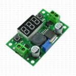
DC->DC Buck Step Down Converter, Voltage Regulator + LED Voltmeter

The SCSI2SD doesn't make use of the 12V line on the Molex connector, no?

I bought one of these for playtime. My notion is to run everything but the PowerCache slot off the 12V rail of the PSU. By my read, converting 12V to 5V with these inexpensive modules might be all we need aside from possibly one big Capacitor to keep current on the auxiliary power plane even.

Have to check the rating spec on the PSU's 12V output, but I'd think 12V requirements of a 1989 HDD ought to be more than sufficient to run up to three PDS cards and a PowerCache?

EE input requested, WAG verification would be most welcome.

edit: to clarify, the object here is to alleviate the necessity for ATX PSU conversion if at all possible.

 
Last edited by a moderator:

joethezombie

Well-known member
Power budget for the PDS slot is 1.5A I believe.  I do wonder what the load is on a PowerCache and what it is on an Xceed.  We will need current limiting electronics to make sure each slot doesn't overdraw.

I'm not an EE, but I was looking at the TI TPS2115.

http://www.ti.com/product/TPS2115

It is a dual in, single out power mux with adjustable current limit and cross conduction blocking.  Here's my idea:

We could place one of these at each slot, with PDS power connected to IN1 and supplemental power connected to IN2 via a floppy drive power connector.  This would allow a user with just an accelerator and network card to just use the adapter without worrying about ATX conversions, supplemental power, or the like.  Just plug and go.  But a heavy user with extreme power requirements could then just simply plug in supplemental power lead, and the power mux would utilize it for each slot that needs it.  We could set the current limit to 1.5A and not worry about over-current or back-feed to the logic board.  If someone wanted to try and use the stock power supply's 12V, they could use jt's step-down converter with a floppy drive power connector hanging off of it.

Thoughts?


Trash80toHP_Mini

NIGHT STALKER
My concern is the overall 5v system requirements vs. the PSU's rated output on the 5V rail. Stepdown from the 12V rail could relieve all stress on the stock PSU if my WAG pans out.

Curiouser and curiouser  .  .  .  next stop on the tech train will be identifying components required to get around the 2 TTL input limited PDS spec.

HELP!!!!!!! :lol:

 
Last edited by a moderator:

Trash80toHP_Mini

NIGHT STALKER
II can also get you the outline measures of the Micron card jt.
You've already posted everything I need but the scan for an exact outline.

/monthly_08_2017/post-46-0-87895500-1504200695.jpg">View attachment 14077

The top edge/upper mounting holes match Apple's spec for the maximum SE/30 expansion card spec. as does my Colorpivot card.

Just held it up against the open SE as if it were in the vertical passthru of my multi-slot AI models. It fits! [:D] ]'>

 
Top