DittoI employ this method and to date have not lifted a single pad. Now that’s I’ve said that I’ve probably jinxed myself
-
Updated 2023-07-12: Hello, Guest! Welcome back, and be sure to check out this follow-up post about our outage a week or so ago.
You are using an out of date browser. It may not display this or other websites correctly.
You should upgrade or use an alternative browser.
You should upgrade or use an alternative browser.
PowerBook 540c Restoration Project
- Thread starter jmacz
- Start date
MacUp72
Well-known member
View attachment 60732
Now for my question. All the caps (EXCEPT two of them) have the negative side on ground. I've tested this with a multimeter. The huge expanse of green on the board is ground (as expected).
But two of the caps, are inverted. I have circled the positive pad for these two caps and it's clear the positive side is on ground. The arrows also indicate how the positive pad is actually connected to the negative pads for the other caps.
Given this, I'm trying to understand if this might cause an issue with tantalums vs electrolytic capacitors? I had thought with tantalums you never want to invert them. If someone could explain how this works that would be great. I want to learn.
it also depends whats on pin6 of the little green board, eg if the IC T145 needs a negative voltage..whats the special purpose of this board?
jmacz
Well-known member
I employ this method and to date have not lifted a single pad. Now that I’ve said that I’ve probably jinxed myself
Ditto
Knock on wood!
it also depends whats on pin6 of the little green board, eg if the IC T145 needs a negative voltage..whats the special purpose of this board?
Ok, well as I slowly swap back to Tantalums, I will further check out that circuit and the voltages.
jmacz
Well-known member
So anyway, two caps come in and I install them. Computer stops working.
I removed them, works again. Installed one of the two, works still. Installed the last, works still.
Never figured out why it did that, but it shows that weird voodoo like this can happen.
LOL... of course. I put one tantalum cap back on at a time and then plug everything back in to test the display. And test the continuity on each end of the cap with where it should be connected to. One by one. And of course, the display works after each cap is replaced and continues working even after the last one...
During the first attempt, I checked continuity from the tab on each end of each tantalum cap to the other component on the board it's connected to. And got good tone. That should have meant each cap was solidly connected to the board. I even used tweezers to nudge each cap to ensure it would not budge.
My hypothesis: I nudged each cap side to side... but that wasn't good enough as the other joint could have prevented it from moving side to side. I needed to also gently push down to see if there was any movement. I did not do that. And when I placed the probe on the tab to test, I must have pushed it enough to gain continuity for the test. Lesson learned.
Although I wasted many hours on debugging this, I'm glad it's working now. Will post some more pictures this weekend.
Final set of changes for this unit:
- Recapped the motherboard (single capacitor).
- Recapped the modem board.
- Recapped the inverter board.
- Recapped the display.
- Display now looks good, no more bleeding.
- Cleaned off corrosion on the magnesium frame and repainted it matte black with rustoleum paint (and ensured each ground contact point was sanded back to raw magnesium -- probably should have just masked it in hindsight).
- Replaced rusted screws all over the board (M2 and M2.5 button head screws).
- Repaired two standoffs that had broken tops -- 3d printed new washer like tops and epoxied them to the remaining part of the standoff (will share pictures later).
- 3D printed new two piece hinge standoffs and used M2.5 brass inserts instead of screwing into the plastic, and epoxied them into place.
- Added epoxy around remaining ok standoffs for added strength.
- Swapped out laptop SCSI drive with a ZuluSCSI laptop version.
Back in my days racing RC cars, I built NIMH battery packs (AAA, AA, and sub-C) and soldered the tabs myself. I know most people go for spot welding these to prevent heat damage, but I never had an issue back in the day as long as you increase the temp on the soldering iron and only applied heat for a split second. I'm going to try and see what happens. If I fail, will figure out how to spot weld them.
croissantking
Well-known member
jmacz
Well-known member
@jmacz do you have a photo of the completed LCD driver board with the tantalums? Just curious how it looks.
Here's a picture.

Note that a couple of the caps have a dark mark on them.. that's because I used a black felt tip marker to mark them as I was testing them trying to figure out what was going on earlier. I was able to remove the marking on the other caps but two or three of them wouldn't come off. Not like I care but just wanted to explain the mark in case anyone was wondering why there's a dark spot on the cap
3lectr1cPPC
Well-known member
Very clean work. Great job! And nice to hear that your LCD works once again.
croissantking
Well-known member
Tidy work, happy to hear it’s all working fine.
cheesestraws
Well-known member
LOL... of course. I put one tantalum cap back on at a time and then plug everything back in to test the display. And test the continuity on each end of the cap with where it should be connected to. One by one. And of course, the display works after each cap is replaced and continues working even after the last one...So they all work and it's all good now.
If it helps, this is basically the kind of thing that happens to everyone. Nice result, though - very neat.
jmacz
Well-known member
Shared the custom power supply connector that I made with instructions, parts, and models in this thread: https://68kmla.org/bb/index.php?threads/powerbook-power-supply-connector-520-520c-540-540c.45148/
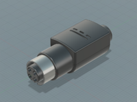
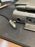
Next up, make my own power supply with this connector.


Next up, make my own power supply with this connector.
croissantking
Well-known member
Love the attention to detail. I wonder what other upgrades or improvements we could do to these old 500 series machines.
jmacz
Well-known member
Finally got around to building the power supply using two 16V 4A power supplies from Amazon:
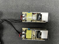
Desoldered the power jack on one of them and spliced them together. Also connected my custom made power connector.
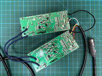
Then 3D printed a new enclosure to house the two power supplies together:
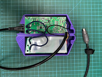
I cut out a piece of mylar and taped it to the back of one of the boards to ensure the boards don't short against each other. Should be fine as mylar is supposed to be a good electrical insulator. And here it is closed up:
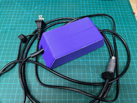
And the unit works and powers my 540c.
I ended up painting the enclosure, but I'm super unhappy with how it turned out... I decided to fill in the seems with some putty, sanded it, and primed and painted it. But the end result just didn't look good. I guess as long as it works it doesn't matter... but if I were to do it again, I probably would not fill the seems or sand it... I would just paint it. Because without that texture, it looks like a lumpy brick I am purposely not posting a picture of the painted result because again, it looks like crap.

Desoldered the power jack on one of them and spliced them together. Also connected my custom made power connector.

Then 3D printed a new enclosure to house the two power supplies together:

I cut out a piece of mylar and taped it to the back of one of the boards to ensure the boards don't short against each other. Should be fine as mylar is supposed to be a good electrical insulator. And here it is closed up:

And the unit works and powers my 540c.
I ended up painting the enclosure, but I'm super unhappy with how it turned out... I decided to fill in the seems with some putty, sanded it, and primed and painted it. But the end result just didn't look good. I guess as long as it works it doesn't matter... but if I were to do it again, I probably would not fill the seems or sand it... I would just paint it. Because without that texture, it looks like a lumpy brick
croissantking
Well-known member
I want to see!I am purposely not posting a picture of the painted result because again, it looks like crap.
I actually think the purple colour is cool. Doesn’t need painting. I like the rawness with the seam etc as you can get a better sense of your design which has a feeling of origami.
croissantking
Well-known member
Also let’s see a close up of the power connector.
jmacz
Well-known member
I actually think the purple colour is cool. Doesn’t need painting. I like the rawness with the seam etc as you can get a better sense of your design which has a feeling of origami.
Yeah, I think I would leave it purple/raw next time as well.
My other thread on the connector has some close ups (you can click on the pictures in that thread to blow it up).
PowerBook Power Supply Connector (520/520c/540/540c)
I wanted to share information on this PowerBook 5xx Power Supply Connector I have been toying with. Been so busy with other projects lately that I only got a chance to play with this a bit more today. I have not yet worked on the actual power supply yet but I wanted to at least share the...
 68kmla.org
jmacz
Well-known member
This past weekend, put together a design for a battery cover which is similar to Apple's. Not exact but I didn't want to spend an incredible amount of time on the CAD so it's good enough?
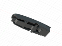
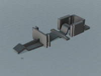
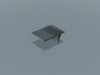
Printed a prototype with my filament printer and it fit but filament based 3d printing just wasn't accurate enough for the detailed parts. So the final one was printed on my 3d resin printer. The below is right out of the printer with the supports cut off.
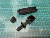
Then with some sanding and painting. Grabbed a spare screw out of my toolbox and cut a few links off so that it would fit and had the right amount of tension.
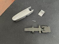
Assembled below... again, could have used some filler, sanded it in the proper sequence of 100 to 1200 grit sand paper, but I did not hence the little imperfections. That's fine. Wasn't planning to make a whole weekend out of this.
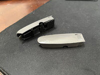
And then installed.
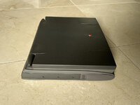
Attached the STL files to this post if anyone wants to print some for themselves.


Printed a prototype with my filament printer and it fit but filament based 3d printing just wasn't accurate enough for the detailed parts. So the final one was printed on my 3d resin printer. The below is right out of the printer with the supports cut off.

Then with some sanding and painting. Grabbed a spare screw out of my toolbox and cut a few links off so that it would fit and had the right amount of tension.

Assembled below... again, could have used some filler, sanded it in the proper sequence of 100 to 1200 grit sand paper, but I did not hence the little imperfections. That's fine. Wasn't planning to make a whole weekend out of this.

And then installed.

Attached the STL files to this post if anyone wants to print some for themselves.
Attachments
mdeverhart
Well-known member
That is outstanding looking, even without the extra work on surface finishing. Great job!
jmacz
Well-known member
One last piece on this project... the front bezel was cracked and will not go back on properly as the little teeth were broken. You can see the missing front bezel here:
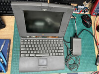
It's where you can see the mic and ribbon cables. So of course, needed to make a new replacement.
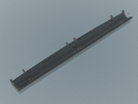
Just like the battery slot cover, the pins were too detailed here and my 3D filament printer just wasn't good enough to print it out. Since I needed to use my 3D resin printer, I needed to split the model into two parts because the printing volume for my 3D resin printer is too small. Here are the parts printed:
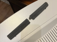
And here's the two pieces glue together with epoxy and installed.
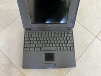
One of these days I will get someone with a larger printer to print a one piece one for me so I can avoid the seam in the middle. I could have filled/sanded but left it for now.
Attached are the STL models for this bezel cover. I have included both a left/right two piece version as well as a one piece version.

It's where you can see the mic and ribbon cables.

Just like the battery slot cover, the pins were too detailed here and my 3D filament printer just wasn't good enough to print it out. Since I needed to use my 3D resin printer, I needed to split the model into two parts because the printing volume for my 3D resin printer is too small. Here are the parts printed:

And here's the two pieces glue together with epoxy and installed.

One of these days I will get someone with a larger printer to print a one piece one for me so I can avoid the seam in the middle. I could have filled/sanded but left it for now.
Attached are the STL models for this bezel cover. I have included both a left/right two piece version as well as a one piece version.
Attachments
Similar threads
- Replies
- 41
- Views
- 2K
