jmacz
Well-known member
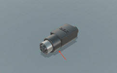
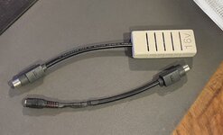
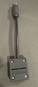
I wanted to share information on this PowerBook 5xx Power Supply Connector I have been toying with. Been so busy with other projects lately that I only got a chance to play with this a bit more today. I have not yet worked on the actual power supply yet but I wanted to at least share the connector incase anyone wanted to give it a try.
My goal was recreate the power connector for the PowerBook 520/520c/540/540c power supply since it seems to be a proprietary connector.
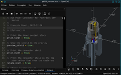
Here's my design/model:
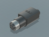
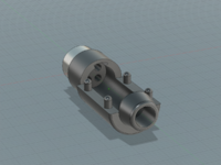
The idea was to 3D print the body/cap and use metal for the shield. I made an initial prototype using filament printing just to make sure the size/structure was correct. It was clear right from the first print that there was no way filament printing was going to provide the precision necessary for the fine holes, etc. So for the real thing, I used a resin printer.
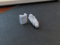
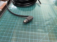
This is straight out of the printer with the supports cut away. The size was good enough and the only sanding I did was to smoothen where the supports were. But the rest of the measurements were good and did not require any sanding.
Now for the metal shield. The shield makes contact with the interior of the power socket (laptop side) and goes to chassis ground within the laptop. I needed something strong but conductive. I opted for stainless steel. Not the best for conductivity but I'm hoping it's good enough (maybe an expert can chime in here). It was testing fine with my multimeter but I'm not an electrical person.
To create the metal shield, I bought a 10mm (outside diameter) stainless steel tube with a wall thickness of 0.5mm which is very close to the stock connector.
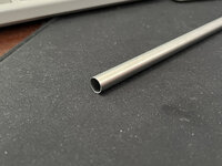
I then cut a 12mm piece off the end using a dremel. Probably should have used my lathe but a dremel worked fine.
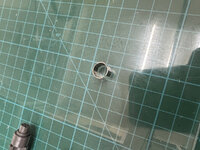
I then cut a 1mm slit in it to make a "C" ring. The 3D printed body has a slot for this ring to fit in. It's a tight fit and snug, it's not coming out. Here's a picture with the shield inserted and the cap in place.
For the actual pins, I bought some of the crimp pins that @Fizzbinn found on Amazon that fit the power pins perfectly. I also purchased a 5mm diameter cable with 5 internal strands, one for each of the 4 pins and 1 for the shield ground. Then soldered/crimped the crimp pins onto four of the strands and soldered the black strand to the shield inside the connector body.
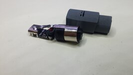
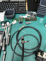
The soldering to the metal shield took some additional thought. It's stainless steel and so will NOT solder using standard solder wire or flux. I had to get special flux made for stainless steel as well as some flux with some silver in it. That worked well. Here's a picture of the assembly.
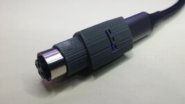
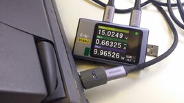
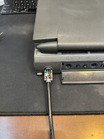
And with it inserted into my PowerBook 540c.
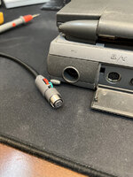
And with the cap on.. note I didn't fully close it as I will most likely epoxy the interior to ensure none of the wires pull out.
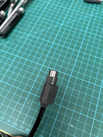
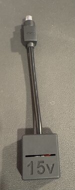
Next step is to build the power supply. I will talk about that in my PowerBook 540c restoration thread.
So as promised, I will attach the STL files to this post. As far as the other parts you will need:
My goal was recreate the power connector for the PowerBook 520/520c/540/540c power supply since it seems to be a proprietary connector.
Here's my design/model:


The idea was to 3D print the body/cap and use metal for the shield. I made an initial prototype using filament printing just to make sure the size/structure was correct. It was clear right from the first print that there was no way filament printing was going to provide the precision necessary for the fine holes, etc. So for the real thing, I used a resin printer.

This is straight out of the printer with the supports cut away. The size was good enough and the only sanding I did was to smoothen where the supports were. But the rest of the measurements were good and did not require any sanding.
Now for the metal shield. The shield makes contact with the interior of the power socket (laptop side) and goes to chassis ground within the laptop. I needed something strong but conductive. I opted for stainless steel. Not the best for conductivity but I'm hoping it's good enough (maybe an expert can chime in here). It was testing fine with my multimeter but I'm not an electrical person.
To create the metal shield, I bought a 10mm (outside diameter) stainless steel tube with a wall thickness of 0.5mm which is very close to the stock connector.

I then cut a 12mm piece off the end using a dremel. Probably should have used my lathe but a dremel worked fine.

I then cut a 1mm slit in it to make a "C" ring. The 3D printed body has a slot for this ring to fit in. It's a tight fit and snug, it's not coming out. Here's a picture with the shield inserted and the cap in place.

For the actual pins, I bought some of the crimp pins that @Fizzbinn found on Amazon that fit the power pins perfectly. I also purchased a 5mm diameter cable with 5 internal strands, one for each of the 4 pins and 1 for the shield ground. Then soldered/crimped the crimp pins onto four of the strands and soldered the black strand to the shield inside the connector body.
The soldering to the metal shield took some additional thought. It's stainless steel and so will NOT solder using standard solder wire or flux. I had to get special flux made for stainless steel as well as some flux with some silver in it. That worked well. Here's a picture of the assembly.

And with it inserted into my PowerBook 540c.


And with the cap on.. note I didn't fully close it as I will most likely epoxy the interior to ensure none of the wires pull out.

Next step is to build the power supply. I will talk about that in my PowerBook 540c restoration thread.
So as promised, I will attach the STL files to this post. As far as the other parts you will need:
- Crimp Pins (thanks @Fizzbinn): https://www.amazon.com/dp/B00EDG0KI4
- Stainless Steel Tube: https://www.amazon.com/dp/B099QLMZLX
- Cable: https://www.amazon.com/dp/B0B942SY29
- Stainless Steel Flux and Solder: https://www.amazon.com/dp/B0015H6JYS

