jmacz
Well-known member
I recently picked up a cheap PowerBook 160 to help test my SD Aide utility. I got it super cheap from a friend. Although it ran and fulfilled its testing purpose, I figured I should fix it up instead of letting it die. It came to me with lots of physical chassis issues (falling apart) and the LCD display did not work (no image, just the backlight turns on).
Display and Electronics
This was apparently the second LCD inside this PowerBook 160. I was told the previous one had died, been recapped, but still didn't work, and so a second LCD was acquired, that worked for a few months but then also died. A new inverter board was also acquired but that did not help. I took the PowerBook apart and here is the display capacitors:

Capacitor leakge was visible, there was some minor corrosion on the pins near the various capacitors. Some of the capacitors were barely hanging on (as you can see from the photos) and one of the pads was lifted (C1) and barely hanging on. The picture above was with the capacitor still on the board but I had cleaned up the corrosion. After removal of the capacitors, you could smell the leak. Yuck. I took the old capacitors off, cleaned the board, fixed the pad, cleaned up the other pads, and put new tantalums on:

@3lectr1cPPC's capacitor list was correct and allowed me to get the capacitors ahead of time so that after taking apart the unit, I could go to work right away instead of reading the capacitor specs and waiting to order the replacements.
The inverter board also needed to be recapped. Although the polymer one probably didn't need to be replaced, I replaced both just to be sure. Also replaced the caps on both of the inverter boards I got with the unit:

While I was at it, I replaced the single capacitor on the trackball unit. The trackball itself was a little sticky so I ended up cleaning the entire mechanism and it works perfectly now.

Lastly for the electronics, I replaced the PRAM coin battery. It's soldered onto a board but easy to remove. I replaced it with a new Panasonic VL2330 lithium battery.

Physical Chassis
As usual, the plastics on this PB160 had degraded over time. Super brittle. I had heard rattling inside the laptop and sure enough, almost all of the standoffs had broken off. Some of the carnage:


Ouch. So had to go and design new parts to replace these stand offs (I will attach the STL files at the bottom of this post). Note the small cylinder and the other part are not part of the standoffs obviously. More on those pieces later.

First was to remove the existing standoffs. Most of it crumbled away but I used a dremel to grind away what was left behind:

Next I used a combination of super glue and epoxy to put in place the 3D printed replacements which were printed with ABS.

Then had to place in the brass inserts. These were the stock brass inserts.

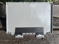
And then back together it went. Everything is working")

Display and Electronics
This was apparently the second LCD inside this PowerBook 160. I was told the previous one had died, been recapped, but still didn't work, and so a second LCD was acquired, that worked for a few months but then also died. A new inverter board was also acquired but that did not help. I took the PowerBook apart and here is the display capacitors:
Capacitor leakge was visible, there was some minor corrosion on the pins near the various capacitors. Some of the capacitors were barely hanging on (as you can see from the photos) and one of the pads was lifted (C1) and barely hanging on. The picture above was with the capacitor still on the board but I had cleaned up the corrosion. After removal of the capacitors, you could smell the leak. Yuck. I took the old capacitors off, cleaned the board, fixed the pad, cleaned up the other pads, and put new tantalums on:
@3lectr1cPPC's capacitor list was correct and allowed me to get the capacitors ahead of time so that after taking apart the unit, I could go to work right away instead of reading the capacitor specs and waiting to order the replacements.
The inverter board also needed to be recapped. Although the polymer one probably didn't need to be replaced, I replaced both just to be sure. Also replaced the caps on both of the inverter boards I got with the unit:
While I was at it, I replaced the single capacitor on the trackball unit. The trackball itself was a little sticky so I ended up cleaning the entire mechanism and it works perfectly now.
Lastly for the electronics, I replaced the PRAM coin battery. It's soldered onto a board but easy to remove. I replaced it with a new Panasonic VL2330 lithium battery.
Physical Chassis
As usual, the plastics on this PB160 had degraded over time. Super brittle. I had heard rattling inside the laptop and sure enough, almost all of the standoffs had broken off. Some of the carnage:
Ouch. So had to go and design new parts to replace these stand offs (I will attach the STL files at the bottom of this post). Note the small cylinder and the other part are not part of the standoffs obviously. More on those pieces later.
First was to remove the existing standoffs. Most of it crumbled away but I used a dremel to grind away what was left behind:
Next I used a combination of super glue and epoxy to put in place the 3D printed replacements which were printed with ABS.
Then had to place in the brass inserts. These were the stock brass inserts.
And then back together it went. Everything is working