jmacz
Well-known member
Picked up a Powerbook Duo 280c the other day.. paid a bit more than I wanted (just slightly) but I had been eyeballing trying out the Duo ecosystem for a while. It came to me working but had a high frequency whine from the screen, the drive was noisy, and I could hear plastic rattling inside. Screen seemed very good though and I started the process of recapping the entire machine to preserve it.
The inside was pretty clean. Nothing out of the norm. It had an Apple 8MB memory card for a total of 12MB. I want/need more but finding a card is going to be difficult. I took the picture after unplugging the lid sensor and the microphone so that's why those cables are unplugged. And I removed the trackball cover.
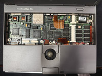
After carefully removing the top of the unit, I found nothing too crazy underneath either. No corrosion in the battery compartment.
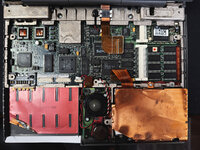
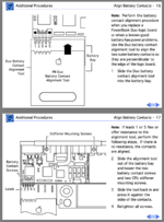
The battery had been a little hard to remove and it looks like that was because the inner lining had been folded over and was adding friction. It was also hard to remove the battery as the unit came with the battery slot cover (which slides onto the battery) but the clips on it were all gone so it doesn't stay attached to the battery. I looked at trying to fix it somehow but the clips are too tiny and it's just not going to work. I will have to either model my own battery cover at some point or find one on eBay.
The trackball wasn't working right... and it was because it was caked in gunk.. yuck.
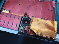
Next I decided to open up the screen... but I couldn't... I carefully removed the front facing screw covers (the little thin squares) and attempted to remove the two screws. They were just spinning and wouldn't come out. The standoffs had broken off inside the case and were just spinning inside. Ugh. I used a spudger to carefully pry open the lid and was lucky enough not to break any clips in the process. Since the standoffs had broken off, the screen came apart easily with the gentle prying.
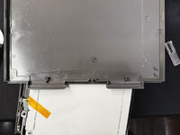
Usual design and usual breakages. The brass inserts were spinning as the plastic was no longer holding it. And of course, the usual speaker mount was broken as well.
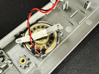
For this, I ended up supergluing it to hold it together and then used a soldering iron to melt the plastic together. I had a ventilator on as ABS fumes are toxic. I then added a bead of epoxy around it to give it extra strength. Next I had to shave off what remained of the standoffs using a dremal and was careful to mark the center of where the insert needs to be.
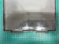
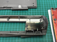
Then modeled replacement standoffs and epoxied them into place. This picture below is before I put the brass inserts back in (I don't have a picture of that). I reused the stock brass inserts. I will include the 3D model of it with this post.
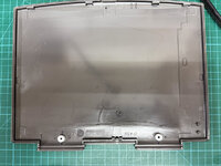
With the lid off, here's the LCD, model Sharp LQ94D041.
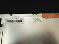
And here's the stock electrolytic capacitors. @3lectr1cPPC here's the picture you wanted.
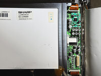
And the inverter board has one as well:
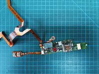
The source of my high frequency whine was this inverter board, or the coils on it (the larger orange coils). I had dealt with coil whine on power supplies before where vibrations in the coil would cause the noise. The resolution was using some hot glue to prevent the coils from vibrating. In this case, the coils were too small so I opted for liquid superglue. I found a few folks online who had done that for their video card coils. I covered the coils in superglue and left it over night. In the morning, the whine was gone.
Surprisingly while removing the stock capacitors, I found no signs of leakage. No fishy smell. Everything looked fine. Go figure.
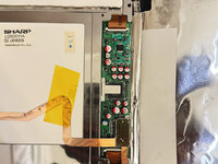
And here's after I had recapped the screen. I used polymer capacitors. In hindsight, I think I might have preferred polymer tantalums. Reason being although the polymer capacitors I used were the same dimensions as the stock ones, what I found is that if you grab the LCD lid hard, you end up pressing on the capacitors. Ask me how I know this... I had a weak solder of one of the capacitors and it broke lose as I grabbed the screen. The polymer tantalums are low profile so that might have been better.
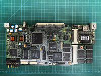
Then it was time to recap the main logic board. Here's a picture of the stock capacitors.
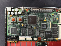
And then replaced with new polymer capacitors.
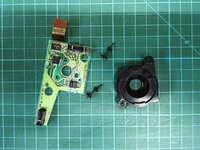
The trackball needed to be cleaned up so I disassembled it and used IPA on a cotton swab to clean everything up.
After that, the trackball worked perfectly.
For the hard drive, I replaced it with a ZuluSCSI. The hard drive mounts from the side so the existing mount won't work for the ZuluSCSI. So I had to make a new mount for it. I will attach the 3D model to this post.
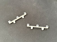
And here it is on the ZuluSCSI.
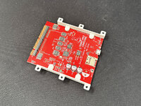
With that it fit right into the chassis.
At that point the laptop was working but keyboard was mushy. This Duo keyboard has to be the worst keyboard I have ever used.
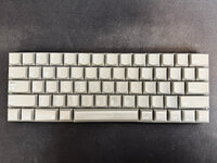
I disassembled it, cleaned up the contacts using deoxit, and also relubed all the key cap stems.
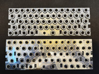
The key action is better but still sucks. I also have a problem with my 'O', 'Delete', and 'Spacebar' keys. The O hardly works. And the Delete/Space Bar are unforgiving .. you have to hit them dead center or else they don't register. I didn't get this resolved and will need to place with it some more or hunt for another keyboard.
With that the main laptop was working fine. It was time to move on to the accessories. First the power adapter. It was working when I got it but I decided to just open it up and replace the caps.
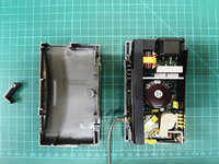
This is the stock unit opened up. I was surprised how easily it came apart. Usually I have to work on it for a while with an X-acto blade, but on this one, I got it open in one pass. The stock unit was missing one of the cable management legs.
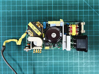
Another view of the stock adapter removed from the plastic.
The missing cable management leg was bothering me so I modeled a replacement. I will attach the 3D model to this post.
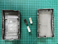
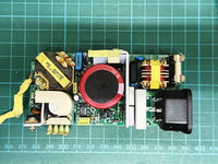
The above is with two new replacements 3D printed. And then here's the after picture with the new caps in place. The small caps were leaking and I saw residue once I removed the caps. As usual, the larger one seemed fine but replaced it anyway.
And then back into the plastic case with the replacement cable management legs.
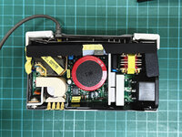
And here it is reassembled. I used super glue to glue the case back together.
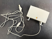
I should paint the legs.. haven't done that yet so they are still white.
Next up was the Duo MiniDock. It came to me working as well. But again I decided to open it up and recap it to preserve it.
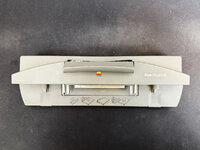
It also had broken plastic rattling inside. It was one of the clips.
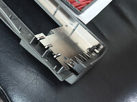
I had to repair that first.
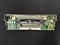
Here's the stock picture of the main board with 4 electrolytic capacitors. I could smell the capacitors as I opened the unit.
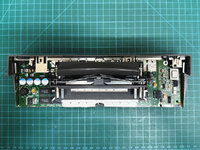
And with the board cleaned up and capacitors replaced again with polymer capacitors.
Next step was the battery. It took some X-acto knifing to get the case open but it finally opened up.
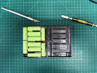
Ten 4/5 A sized cells. I replaced them with new ones of the same physical size. The new cells had 2000mAH capacity.
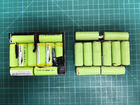
I spot welded them together and they fit in the case exactly the same way the original cells did. The thermistor, fuse, and ID chip were all moved from the original pack to the new one. And then I held the case together using kapton tape.
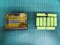
The cells on the right are the stock cells. They will be going to the hazardous waste management office.
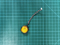
Also replaced the PRAM battery with brand new cells.
So where am I now?
The Duo works except the 3 keys that I mentioned before. I need to spend some more time trying to fix that. If I can't, time to hunt for a replacement keyboard.
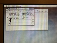
The battery however is not working. The fuse is good. The cells are also good as I see 12.3V across the +/- terminals. When inserted into the Duo, it sees the battery and the attempts to charge it even though it shows as full in the Control Strip. My multimeter also shows a 12.3V on the pack. But the Duo refuses to boot from the battery pack. Not quite sure what's going on there. I have reset the power manager already and also zapped the PRAM. Maybe the ID chip is dead?
Anyhow, attached the 3D models for the plastic pieces I made to this post.
The inside was pretty clean. Nothing out of the norm. It had an Apple 8MB memory card for a total of 12MB. I want/need more but finding a card is going to be difficult. I took the picture after unplugging the lid sensor and the microphone so that's why those cables are unplugged. And I removed the trackball cover.

After carefully removing the top of the unit, I found nothing too crazy underneath either. No corrosion in the battery compartment.

The battery had been a little hard to remove and it looks like that was because the inner lining had been folded over and was adding friction. It was also hard to remove the battery as the unit came with the battery slot cover (which slides onto the battery) but the clips on it were all gone so it doesn't stay attached to the battery. I looked at trying to fix it somehow but the clips are too tiny and it's just not going to work. I will have to either model my own battery cover at some point or find one on eBay.
The trackball wasn't working right... and it was because it was caked in gunk.. yuck.

Next I decided to open up the screen... but I couldn't...

Usual design and usual breakages. The brass inserts were spinning as the plastic was no longer holding it. And of course, the usual speaker mount was broken as well.

For this, I ended up supergluing it to hold it together and then used a soldering iron to melt the plastic together. I had a ventilator on as ABS fumes are toxic. I then added a bead of epoxy around it to give it extra strength. Next I had to shave off what remained of the standoffs using a dremal and was careful to mark the center of where the insert needs to be.

Then modeled replacement standoffs and epoxied them into place. This picture below is before I put the brass inserts back in (I don't have a picture of that). I reused the stock brass inserts. I will include the 3D model of it with this post.

With the lid off, here's the LCD, model Sharp LQ94D041.

And here's the stock electrolytic capacitors. @3lectr1cPPC here's the picture you wanted.

And the inverter board has one as well:

The source of my high frequency whine was this inverter board, or the coils on it (the larger orange coils). I had dealt with coil whine on power supplies before where vibrations in the coil would cause the noise. The resolution was using some hot glue to prevent the coils from vibrating. In this case, the coils were too small so I opted for liquid superglue. I found a few folks online who had done that for their video card coils. I covered the coils in superglue and left it over night. In the morning, the whine was gone.
Surprisingly while removing the stock capacitors, I found no signs of leakage. No fishy smell. Everything looked fine. Go figure.
And here's after I had recapped the screen. I used polymer capacitors. In hindsight, I think I might have preferred polymer tantalums. Reason being although the polymer capacitors I used were the same dimensions as the stock ones, what I found is that if you grab the LCD lid hard, you end up pressing on the capacitors. Ask me how I know this...

Then it was time to recap the main logic board. Here's a picture of the stock capacitors.

And then replaced with new polymer capacitors.

The trackball needed to be cleaned up so I disassembled it and used IPA on a cotton swab to clean everything up.

After that, the trackball worked perfectly.
For the hard drive, I replaced it with a ZuluSCSI. The hard drive mounts from the side so the existing mount won't work for the ZuluSCSI. So I had to make a new mount for it. I will attach the 3D model to this post.

And here it is on the ZuluSCSI.

With that it fit right into the chassis.
At that point the laptop was working but keyboard was mushy. This Duo keyboard has to be the worst keyboard I have ever used.

I disassembled it, cleaned up the contacts using deoxit, and also relubed all the key cap stems.

The key action is better but still sucks. I also have a problem with my 'O', 'Delete', and 'Spacebar' keys. The O hardly works. And the Delete/Space Bar are unforgiving .. you have to hit them dead center or else they don't register. I didn't get this resolved and will need to place with it some more or hunt for another keyboard.
With that the main laptop was working fine. It was time to move on to the accessories. First the power adapter. It was working when I got it but I decided to just open it up and replace the caps.

This is the stock unit opened up. I was surprised how easily it came apart. Usually I have to work on it for a while with an X-acto blade, but on this one, I got it open in one pass. The stock unit was missing one of the cable management legs.
Another view of the stock adapter removed from the plastic.

The missing cable management leg was bothering me so I modeled a replacement. I will attach the 3D model to this post.

The above is with two new replacements 3D printed. And then here's the after picture with the new caps in place. The small caps were leaking and I saw residue once I removed the caps. As usual, the larger one seemed fine but replaced it anyway.

And then back into the plastic case with the replacement cable management legs.

And here it is reassembled. I used super glue to glue the case back together.

I should paint the legs.. haven't done that yet so they are still white.
Next up was the Duo MiniDock. It came to me working as well. But again I decided to open it up and recap it to preserve it.

It also had broken plastic rattling inside. It was one of the clips.

I had to repair that first.

Here's the stock picture of the main board with 4 electrolytic capacitors. I could smell the capacitors as I opened the unit.

And with the board cleaned up and capacitors replaced again with polymer capacitors.

Next step was the battery. It took some X-acto knifing to get the case open but it finally opened up.

Ten 4/5 A sized cells. I replaced them with new ones of the same physical size. The new cells had 2000mAH capacity.

I spot welded them together and they fit in the case exactly the same way the original cells did. The thermistor, fuse, and ID chip were all moved from the original pack to the new one. And then I held the case together using kapton tape.

The cells on the right are the stock cells. They will be going to the hazardous waste management office.
Also replaced the PRAM battery with brand new cells.

So where am I now?
The Duo works except the 3 keys that I mentioned before. I need to spend some more time trying to fix that. If I can't, time to hunt for a replacement keyboard.
The battery however is not working. The fuse is good. The cells are also good as I see 12.3V across the +/- terminals. When inserted into the Duo, it sees the battery and the attempts to charge it even though it shows as full in the Control Strip. My multimeter also shows a 12.3V on the pack. But the Duo refuses to boot from the battery pack. Not quite sure what's going on there. I have reset the power manager already and also zapped the PRAM. Maybe the ID chip is dead?
Anyhow, attached the 3D models for the plastic pieces I made to this post.

