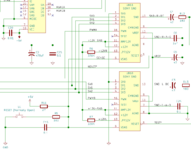
• Updated 2023-07-12: Hello, Guest! Welcome back, and be sure to check out this follow-up post about our outage a week or so ago.

SE/30 - no bong, no video before and after logic board recap

obsolete

Well-known member
First of all, I'm new to the forum but have been reading and soaking up as much information as I can for the past few weeks. Wow, what a wealth of knowledge here. I love this place!

I have an SE/30 that I'm trying to resurrect. I've had this machine since I was a kid. It used to work, then sat after I went to college. A few years after I graduated, I took it out and powered it up again; simasimac. I attempted to recap it at that time, but my soldering equipment and skills were both garbage. My memory is a little hazy, but the recap didn't help, and I suspect I made it worse. I got discouraged and put it in a closet. 10 years later, I realized that I have the skills and equipment to fix it properly now. Its current symptoms are no bong, no video. Here's what I've done so far:

  • Removed RAM, ROM, socketed PALs and video ROM, all electrolytic caps, UA8-UG8, UB12, UC12, RP2 and RP3
  • Cleaned the board with ammonia and a toothbrush, rinsed with distilled water, then cleaned again with 91% isopropyl and baked at 170F for 30 mins
  • Scraped back damaged solder mask from traces around C3-C6, UB10-UB12, UC12-UE12, RP2 and RP3
  • Tinned exposed copper, verified continuity, repaired a broken trace under RP3, then removed flux and covered all trace repairs with green overcoat pen
  • Replaced all radial electrolytic caps with new 25V-50V tantalums
  • Replaced UA8-UG8, UB12, and UC12 with new parts. Repaired one torn off pad at UC12
  • Cleaned, tested, and reinstalled the RP2 and RP3 filters
  • Replaced axial caps with new higher rated parts
  • Fixed a cracked solder joint on Y3
  • Added a bodge wire from the + side of C11 to pin 13 on the J12 power & video connector. Apparently I damaged this via during my first recap attempt
  • Reflowed all pins on J12
  • Wiped RAM, ROM, PAL, and video ROM pins with deoxit D5 before reinstalling
  • 3D printed potatofi's ROM clips and used them securely install the ROM in the socket since it has one broken clip
Yeah, a bit of a shotgun approach. After all that work, I have the exact same symptoms; no bong, no video. The CRT heats up; I can see the little orange glow in the neck. The analog board and power supply are both good. I have a working SE, and the SE/30 works fine with the SE logic board in it, so its analog board and power supply are good. I tried the SE/30 logic board in the SE too, and it has the same symptoms there; no bong, no video, so the problem is definitely in the logic board.

My only theory at this point is that maybe there was an internal layer connection at the + side of C11 that is still broken. Would testing voltages at the floppy connector help rule that in/out? The schematic is helpful but I don't have a good idea of what the 5V plane looks like. Any other theories would be very much appreciated. Thanks!
 

bigmessowires

Well-known member
My SE/30 sometimes won't boot even with its original ROM, even with PotatoFi SIMM clips. The ROM socket seems particularly prone to wear. You might try booting while pulling or pushing on the ROM SIMM, or even replacing the whole ROM SIMM socket.

Have you used the schematic to start verifying connections between the CPU, bus chips, ROM socket, and other support chips?

From the schematic, C11 is the main bulk capacitor for the +5V supply. The - side should have continuity to ground and the + side to +5V on the logic board and the supply connector.
 

obsolete

Well-known member
Thanks. I tried pushing and pulling the ROM SIMM today to no avail. I poked around with the meter a little bit and found that +5V seems to be getting everywhere that it should. The only odd thing I found is that there's no -12V at the floppy connector like there is on my SE, but maybe the SE/30 board just doesn't have that pin wired? I believe that -12V is only used for sound and shouldn't prevent the computer from booting, right? I verified that I have -12V at the J12 connector, C48, Q2, and UA9. Oh yeah, I forgot it in my first post, but I replaced UA9 as well.

I think I'll start beeping out more traces tomorrow as you suggested, @bigmessowires
 

kefkafloyd

New member
Do you have reset and clock? Bust out a logic probe and start checking for activity.

Also check continuity on the 5V to the clock from the iron ferrules on the bottom of the board (L12, 13, 14). I had a similar problem on my SE/30 (no video or bong), the issue was that it didn't have clock because ferrule L13 was cracked and thus the crystal wasn't getting any 5V power. Replacing the ferrule fixed the break and got the machine working again.


obsolete

Well-known member
Thanks for the ideas, I'll check there. All I have at home is a multimeter, but I could take the board into work over the weekend and hook it up to an oscilloscope.

Since I last posted, I've beeped out all the contacts on the ROM: address lines to the F258s, data lines to the diodes/RAM slots, and 5V and GND are all good. I tested from the SIMM itself, so I know it's making a good connection through the socket.
 

obsolete

Well-known member
I finally made some progress on this tonight. Long story short, I think something's holding down RESET. I have 0.8V on pin 5 of both sound chips UB10/UB11. I see 4.88V on pin 6 of both chips, so it's not the reset switch. I guess the next step is to try pulling UB11? I think it's weird that both chips' RESET pins are low when only UB11 is connected to the rest of the system and UB10 is just connected to a test pin.
 
Last edited:

GRudolf94

Well-known member
Weird, but not entirely unheard of, having both Sony chips fail. Solid troubleshooting effort thus far. Pulling UB11 and looking at /RESET again will soon tell you if that was your problem.
 

obsolete

Well-known member
Thanks. Hopefully I'll get a chance to pull those chips this weekend. There was definitely cap goo in that area.

There's no reason the machine can't boot without the sound chips, is there?
 

croissantking

Well-known member
There's no reason the machine can't boot without the sound chips, is there?
It definitely won’t boot without one of those Sony chips - the one of which controls the reset line. I tried this.

You should be seeing a simasimac display if it was a problem with the machine not coming out of reset though, I think. It sounds possibly like a power issue, or an issue with the GLUE and/or the video circuitry.
 

croissantking

Well-known member
Sorry, I was wrong. I just tried booting a board without the sound chips in, and it worked. Just the reset button doesn't do anything, and there's no sound, obviously.
 

GRudolf94

Well-known member
Hmm, I forget - isn't the reset button wired into the /RESET line directly? If it's wired into pin...6 I think, of UB11, then yeah, it shouldn't work.

I never understood Apple's decision of bunching power-on reset together with audio.
 

obsolete

Well-known member
Hmm, I forget - isn't the reset button wired into the /RESET line directly? If it's wired into pin...6 I think, of UB11, then yeah, it shouldn't work.

I never understood Apple's decision of bunching power-on reset together with audio.

It's weirder than that:

1702750356486.png

The reset switch, S1, pulls pin 6 down through a 100 ohm resistor, but pin 6 is absurdly strongly pulled up to 5V through a 27 ohm resistor, so the lowest S1 is going to be able to pull down pin 6 is just slightly under 4V. I verified these resistor values on my board and they are correct. So this reset circuit is going to dissipate almost 200mW when S1 is pressed. I mean, these are 1/4 watt resistors, so it's fine, just seems odd to me.

The CPU, the FPU, the VIAs (UK11, UK12), the ADB chip, the SWIM chip, the SCSI chip, the OSC (UE10), and of course, the right channel sound chip at UB11 are all connected to RESET. I'm not sure whether any of the others are capable of pulling it down, or if it's strictly an input on everything except the sound chips. Anyway, because pin 5 on UB10 is also low, I pretty strongly suspect that UB11 is the culprit.
 

GRudolf94

Well-known member
Ah, there, I forgot how that was wired. Shoulda looked at the schematics but on the phone that's no fun.

UB11 and the m68k are the only things able to drive /RESET in the whole machine. Of course, nothing to stop a pin on any of those other ICs being shorted, but as far as actually being meant to assert the line by design goes, those are the only two.
 

obsolete

Well-known member
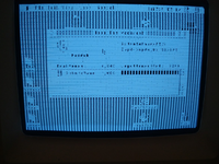
Progress! Hello old friend:
1702786614243.png

After removing the sound chips, this is a huge improvement, but obviously we still have problems. In addition to the white bars, there are intermittent black pixels that flicker all over the screen, more when there's hard drive access or mouse movement. Windows get garbled and (even more) unreadable if you drag them around.

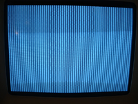
I'm guessing this is a memory problem? The picture above is actually of the second boot. On the first boot, I was overly ambitious and installed all eight 4MB sticks of ram. I got no mouse cursor, and a slightly different, more jagged white bar pattern:
1702787130359.png

After removing the 4 sticks in bank B, I was able to boot successfully and take the first picture above. I then pulled all the RAM, put the 4 sticks from bank B on the first boot into bank A, and tried booting again to confirm whether one of them is bad. Yep, jagged white bars, no mouse cursor, no boot, just like the second picture, so one of those sticks of RAM must be bad, right? I pulled that RAM out and put the "good" 4 sticks back in bank A with bank B empty, just like the successful boot earlier, and...same problem! I pulled those out, reinstalled them in bank A again but with the sticks in a different order, and it booted!

So, could I have one or more bad RAM slots? I vaguely remember this machine being "finicky" about RAM back when I upgraded it 32MB in high school, but can't recall any details other than I got it to work back then. I really dread trying to desolder a RAM slot...
 

GRudolf94

Well-known member
I wouldn't fiddle with the RAM slots unless they were visibly bad, though some deoxit might be advisable in any case.
Just to be sure you're getting consistent behavior, I'd lift R7 and short pin 5 to 6 on the footprint for UB11, so you can manually reset the machine at power-on and guarantee it's all coming up in unison as designed.
 

croissantking

Well-known member
What kind of ROM are you testing with? If you can get your hands on a Rominator II (or any variant based on the IIsi ROM, really) you’ll have more flexibility as regards RAM installation. For example, you’ll be able to boot with bank B populated and bank A empty. I found this really useful for troubleshooting a RAM issue on one of my boards.

The video issues seem like a separate problem to me, possibly a bad VRAM or PAL chip? You say you’ve replaced the F253, LS166 and LS393 chips so we can be confident in those parts, though there could still be a bad trace in that area.
 

GRudolf94

Well-known member
You say you’ve replaced the F253, LS166 and LS393 chips so we can be confident in those parts, though there could still be a bad trace in that area.
This. Every missing bit of screen seems to be 8px wide - as if UE8 (which serializes video data from the video RAMs) was only being loaded every other cycle. Trying to figure out what else could that mean. I'd still first check that the machine is being wholly reset, but...
 

obsolete

Well-known member
I wouldn't fiddle with the RAM slots unless they were visibly bad, though some deoxit might be advisable in any case.
Just to be sure you're getting consistent behavior, I'd lift R7 and short pin 5 to 6 on the footprint for UB11, so you can manually reset the machine at power-on and guarantee it's all coming up in unison as designed.
That makes sense, I will give it a try. Assuming you mean R11 (27ohm)?
What kind of ROM are you testing with? If you can get your hands on a Rominator II (or any variant based on the IIsi ROM, really) you’ll have more flexibility as regards RAM installation. For example, you’ll be able to boot with bank B populated and bank A empty. I found this really useful for troubleshooting a RAM issue on one of my boards.
Oh, I didn't know that, thanks for the info. I'm still using the SE/30 ROM. I've been eyeing a ROMinator II (and a Floppy Emu, and a Wombat...), but maybe after Christmas since I've already spent enough on Mac stuff this year!
The video issues seem like a separate problem to me, possibly a bad VRAM or PAL chip? You say you’ve replaced the F253, LS166 and LS393 chips so we can be confident in those parts, though there could still be a bad trace in that area.
This. Every missing bit of screen seems to be 8px wide - as if UE8 (which serializes video data from the video RAMs) was only being loaded every other cycle. Trying to figure out what else could that mean. I'd still first check that the machine is being wholly reset, but...
I agree. I haven't played with it too much, but when it boots, are are no signs that the computer isn't operating normally. It starts up and shuts down like you'd expect, applications open and close normally, etc. Yesterday, I beeped out all the traces from the F253 video muxes (UA8-UD8) and the LS166 shift register (UE8) to the VRAMs, Video ROM, PALs, and PDS socket. No issues found. I haven't finished checking all the pins on the PALs and LS393s but will do soon.

Luckily, I finally found a decent deal on another SE/30 motherboard. It's still in original non-recapped condition, but at least it has known good video, so I'll be able to swap stuff like PALs and Video ROM back and forth for troubleshooting once it arrives.
 
Top