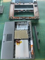
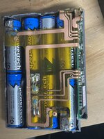
How do you model stuff like that? I want to learn how to do complex parts like that for my own Powerbook
I've been using Fusion 360 and it's just time/practice. Fusion's not as great if you have more freeform arbitrarily curvy/blobby objects (I think something like Blender might be better for that) but for more engineering/technical models, it's very intuitive and easy, because Fusion 360 is a parametric modeler (you design things with dimensional input parameters and if you get something wrong, you go back to change that one dimension and the entire model -- if you designed it right -- updates automatically so you don't have to redo the entire design). As long as you can think in terms of 2D layout in X/Y/Z, and have a good set of calipers to measure with sub-millimeter precision, it's very straightforward. Lots of tutorials on YouTube if you want to get started. Many years ago, I found that some of the early Fusion 360 tutorials from NYCCNC were easy to follow and covered a lot of the basics.
There are also a lot of assumptions you can make to get the model close to where you need it to be, after which you can further dial it in. By assumptions what I mean is that the original engineers also relied on circles, ellipses, rectangles, etc so rarely do you find arbitrary curves for these types of parts. They also usually aligned against solid metric or imperial values (ie. millimeters or half of millimeters... ie. 3.0mm, or 3.5mm, rather than 3.38mm) so that makes getting things close pretty easy. For example, if you measure and you get 3.03mm, it's probably 3mm. Within a few measurements, you can figure out if a part was designed in metric or in imperial (american standard). So if imperial, and you get like 0.241 inches, it's probably 0.25in or 1/4 inch. Same with any holes. They are almost always standard sizes. So you're usually looking at holes designed for M2, M2.5, M3, M4 sized screws. You don't see random sizes. This all helps.
After that it's really spending the time to measure against the right dimensions, the right anchor points for parametric design so that if you get something wrong and need to update that one dimension later after you test fit, that every other dimension automatically adjusts based on that change later. And that comes with experience/time/practice.
Anyhow hope this helps. CAD is really fun and to be honest, I get a lot of enjoyment modeling these parts. It's interesting, it's sometimes challenging, it's like a puzzle.
But it's also a slippery slope... because once you get into CAD, you start itching to get into CAM where you think about manufacturing the part ie CNC machining. Putting together the sequence of cuts with speeds/feeds/tooling via CAM is tons of fun and interesting. I spend time manufacturing parts in aluminum as well. LOTS of fun. I'm by no means an expert or even very advanced. But I think I know enough to at least design parts like this.


