• Updated 2023-07-12: Hello, Guest! Welcome back, and be sure to check out this follow-up post about our outage a week or so ago.

500-series alternative power supply learnings

alexGS

Well-known member
I have a 500-series power supply that worked beautifully after a re-cap - then after a week or two, it went pop. It seemed a MOSFET had shorted - and then a spark jumped from that to the transformer leg, eroding a PCB track. But actually, the MOSFET tested fine on removal. The problem appears to be a shorted diode (on the ‘daughtercard’) but that glass diode has blue, yellow, and red lines, and it has me stumped trying to identify a replacement for it.

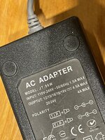
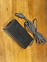
Anyway; that’s just the backstory. I decided to use an alternative 16V power supply with the cable/plug from the failed unit. A visit to a computer recyclers presented almost nothing but piles of 19V supplies. I came home with this no-brand selectable-voltage unit, emblazoned with ‘Power’, carefully chosen because of having a case that is screwed together. It was also cheaper than a USB-C PD cable.

I was concerned at the lightweight electronics within - how could this replicate the function of the original power supply? - but the 4.5A current rating seemed generous. It was very easy to attach the cable neatly, and even easier to remove the switch slider (so the voltage cannot be changed) and blank the resulting slot using a piece cut from a (dead) 5-1/4” floppy disk :)

I wired both Vmain and Vbatt to the power supply and checked that the voltage was close to 16V (16.2).

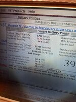
I plugged it into a ‘spares’ machine (not my favourite) and powered it up with no trouble. I started EMMPathy and installed a working battery in the right slot.

I saw something I have not seen before - after the testing-cells phase, the Bulk Charge phase showed a current into the battery of over 3 amps! It is usually around 1 amp. Voltage also shot up to over 12V, where it would usually be about 10.5V at that point in the charge cycle.

I can’t see that would be too good for the battery and I’m surprised it didn’t blow the fuse.

I think I now have the answer to my questions of
1 - “why did Apple fit two separate power supplies into the AC adapter?” and
2 - “can you connect both wires to one supply?”

Answer 1 - because the battery-charging supply (Vbatt) is current-regulated to about 1A, and that controls the charge rate and voltage.

We know the two supplies are not identical, not only from what is printed on the label, but also from the experience of one of us who switched the wires and ran the Powerbook from Vbatt, and found there was not quite enough power with screen brightness up and hard drive in use etc. This tallies with the current figure shown in EMMPathy of around -920mA when the battery is discharging.

It seems the second supply (Vmain) is conventional, voltage-regulated not current-regulated, and the Powerbook draws just what it needs to run.

Answer 2 - no. If you do so, the battery will charge at the maximum current available (almost as though Apple were keeping their options open for providing a fast-charge solution). It seems the current available would depend on the power supply, and then what is left after the demand of running the Powerbook (which varies).

If you tried to run both Vbatt and Vmain from a 1A supply, there wouldn’t be enough current to run the Powerbook and charge the battery.

I suppose you might get away with a 2A supply shared for both, but it seems that the supply for Vbatt should be a current-limited type.

For example, a replacement with a capacity to supply 2A may not be satisfactory, as it seems the battery charging would attempt to draw all of that and more, and the power supply may fail in an undesired fashion, rather than supplying its maximum rated current. Voltage may drop and charging may stop. I tried setting this supply to 15V and found that battery charging wouldn’t start at all.

Anyway, I will be selling one of my Powerbook 520s rather cheap (on account of its damaged casing, 3D-printed parts, etc.) and will not include a battery. I will wire this power supply to VMain only and will label it “not for battery charging”. Then, the other two nicer machines will retain the two original power adapters that I have which both work fine.

Just my musings, hope this helps someone who has rebuilt a battery and may be wondering what to do for a power supply.

Please see also the thread at https://68kmla.org/bb/index.php?threads/pb-5xx-original-ac-adapter-re-cap-modern-replacement.38426/ which seemed to leave the question of whether batteries would charge correctly with Vmain and Vbatt tied together.
 

Attachments

  • IMG_6396.jpeg
    IMG_6396.jpeg
    2.9 MB · Views: 17
  • IMG_6395.jpeg
    IMG_6395.jpeg
    1.7 MB · Views: 17
  • IMG_6394.jpeg
    IMG_6394.jpeg
    2.9 MB · Views: 17
Last edited:

3lectr1cPPC

Well-known member
You're probably correct here, but I'd still be curious to see what happens when using a higher-quality AC Adapter. To any PSU experts out there, do some cheap supplies just always output the max amount of amps they can handle, or is that just not a thing?

Assuming you are right, I'm gonna have to redo my custom PSU once I rebuild my batteries. That, or I could use my original that has a working VBATT but a dead VMAIN.
 

mdeverhart

Well-known member
To any PSU experts out there, do some cheap supplies just always output the max amount of amps they can handle, or is that just not a thing?
I don’t know if I’d sign up for “PSU expert”, but generally speaking a power supply should be able to deliver their rated current (Amps) while maintaining their output voltage. Current is a “pull” (device draws what it needs) rather than a “push” (supply pushes some value). The problem comes when you have a device that expects a current limited supply (doesn’t self regulate its draw for some reason, either intentionally or unintentionally, like a short).

A higher quality supply might have a fuse / resettable-fuse to limit the output current in the case of an overcurrent or short situation. A cheaper supply will often try to keep supplying the load regardless of the amount of current required, resulting in a voltage droop on the output. An even cheaper supply will do the same thing, but will start dropping voltage significantly before it hits the “rated” current output. And of course, the worst supplies are literally a fire hazard…

@alexGS great find and write-up! Glad to have some evidence of why there are separate supply lines on the 500 series supplies. It would be interesting for someone to tear down an old supply and see if they can find evidence of a 1A current limit on the Vbatt supply.
 

cheesestraws

Well-known member
or is that just not a thing?

This isn't generally how things work. The amperage rating on a PSU is the maximum it can source while keeping its output voltage stable and within spec. The amount of current drawn is regulated by the load, not by the power supply.

You do get things called current sources, but they work differently: they have a maximum voltage they will produce, and they will regulate their output to keep the current constant by varying the voltage, instead of keeping the voltage constant as a normal PSU does.

It is not possible to keep both constant for a given load, because each depends on the other.

The amount of current a load draws can be determined either by physics or by design (or both). An old-style incandescent light bulb, for example, is self-regulating, and a perfect resistive load will follow ohms' law.

Other loads will cheerfully draw enough current to self-destruct. An LED is a good example of this: if you just put too high a voltage across an LED, the LED will draw enough current to physically destroy itself. To stop it doing this, you need to limit the current that the LED sees, and you can either put that current limiting in the circuit next to the LED (as is usually done) or in the power supply (as is done in some LED lighting systems).

Batteries are kind of similar. If you attempt to charge many batteries just by sticking a voltage across them, the battery will essentially try to equalise with the voltage across it, and may draw a lot of current in doing so. But this is really bad for the battery, and again, the battery will quite cheerfully damage itself, possibly catching fire in the process in extreme cases. Much like the LED, you need current limiting, and much like the LED, this current limiting can either be built into the device the battery is in, or it can be in the external power supply. Most often in modern consumer electronics, the current regulation is done in the device in the interests of everyone's safety and sanity; but a number of older laptops had the current limiting and charging logic in the charger brick, rather than in the laptop itself - I have others that do likewise.

So if you have a laptop that relies on the charger brick for a separate current limited supply, you really don't want to remove that current limit, because the circumstances with either be subtly or unsubtly bad, but they won't be good. :)

Does that help?
 

jmacz

Well-known member
This is interesting... I would have thought the current would have been limited somehow either in the circuit board within the battery, or on the laptop's mainboard. If it's truly in the vbatt half of the stock charging brick, then I guess my rebuilt power supply won't work. I have yet to test it with the batteries (which I guess is a good thing). My rebuilt unit is two 16V 3A supplies, one for vmain, one for vbatt. The replacement NIMH pack I have is supposed to be charged at less than 2A.
 

jmacz

Well-known member
BTW, on the board inside the battery pack:

Screenshot 2023-10-25 at 10.35.23 AM.png

The blue arrow is connected to the (-) terminal on the outside of the pack. The yellow arrow is connected to the (-) end of the battery pack. They are bridged by the metal thing pointed at by the red arrow. It's one piece metal, has some S curves in it, has almost zero resistance. What is it for?
 

alexGS

Well-known member
This is interesting... I would have thought the current would have been limited somehow either in the circuit board within the battery, or on the laptop's mainboard.
Exactly - I was surprised at how the voltage and current weren’t controlled when the greater current was available.

cheesestraws and mdeverhart have explained it perfectly. I think the Vbatt half of the original supply is a “current source”. It regulates its voltage to provide a maximum of 1A to the load.

A replacement for the Vbatt half will need to work like a bench power supply set to 16V and 1A, operating in ‘controlled current’ mode.

The Vmain half seems conventional and easily replaced by any 16V supply (‘controlled voltage’).
 
Last edited:

alexGS

Well-known member
BTW, on the board inside the battery pack:

View attachment 64299

The blue arrow is connected to the (-) terminal on the outside of the pack. The yellow arrow is connected to the (-) end of the battery pack. They are bridged by the metal thing pointed at by the red arrow. It's one piece metal, has some S curves in it, has almost zero resistance. What is it for?
That is a ‘shunt’ - a precisely-known (very low) resistance in series with the cells, across which a tiny voltage is measured by the battery’s controller. This voltage is proportional to the current flowing in, or out, of the battery cells. Current is measured in series, voltage is measured in parallel.

The resistance of the shunt must be low so as not to dissipate heat (waste power) - you can imagine it interfering with the battery charging or output if it were, say, 1 ohm. V=IR. One volt would be lost if there was one amp flowing through a one ohm resistance. Instead, it will be more like 0.01ohm.

It’s also constructed like that (with air around it) so that it does not heat up, which would alter the resistance and thus corrupt the current reading.

EMMpathy (for example) displays the current reading (in mA). Although it seems the battery controller cannot regulate that current, it probably uses the measurement over time to calculate battery capacity and estimate run-time for the machine.
 
Last edited:

jmacz

Well-known member
That is a ‘shunt’ - a precisely-known (very low) resistance in series with the cells, across which a tiny voltage is measured by the battery’s controller. This voltage is proportional to the current flowing in, or out, of the battery cells. Current is measured in series, voltage is measured in parallel.

Ah. Thanks!
 

cheesestraws

Well-known member
This is interesting... I would have thought the current would have been limited somehow either in the circuit board within the battery, or on the laptop's mainboard

I would have, as well! I do not have a 500 series, but I have at least one other laptop here that also does it in the power brick, so there is precedent...
 

jmacz

Well-known member
A replacement for the Vbatt half will need to work like a bench power supply set to 16V and 1A, operating in ‘controlled current’ mode.

The vbatt half of my charger was 4A, not 3A, so even worse! Good thing I hadn’t tried it with a battery yet. So is this as simple as adding a current controlling circuit, either transistor or IC based to my vbatt half?
 

alexGS

Well-known member
The vbatt half of my charger was 4A, not 3A, so even worse! Good thing I hadn’t tried it with a battery yet. So is this as simple as adding a current controlling circuit, either transistor or IC based to my vbatt half?
I think so, yes. I don’t know how to add a current-controlling circuit, so perhaps if you find one, please let us know, I’d be keen to try it :) I guess then a single power supply can be used, with the current-controlling circuit acting on the Vbatt line, and the full power supply current available on the Vmain line.
 

jmacz

Well-known member
I picked up a cheap constant current + constant voltage module off Amazon ($6) just to play with. The description says it supports from 7V-35V input and can adjustably output 1.25V-30V at up to 3A max.

I used my bench power supply to generate 20V at 2.5A and sent it to some power resistors with a multimeter in between. Without anything, I was seeing 20V @ 2.5A. With the module in place, I was able to use the adjustment pots to limit the voltage to 16V and current to 2A.

But, the thing whines as you limit more current and as expected, it gets hot. I used a temperature gun to measure the heat on the major board components. The capacitor on the input side of the board was quickly getting to 150F and higher. I shut it down after that.
 

alexGS

Well-known member
Thanks for testing!
Running hot reminds me of the cheap Li-ion battery-charging boards I bought, I suppose they would be operating on a similar principle.

So it wasn’t going to achieve the limit of 16V/1A easily? I guess that will need a lower-rated power supply.
 

jmacz

Well-known member
Thanks for testing!
Running hot reminds me of the cheap Li-ion battery-charging boards I bought, I suppose they would be operating on a similar principle.

So it wasn’t going to achieve the limit of 16V/1A easily? I guess that will need a lower-rated power supply.

I was going to play with it some more this coming weekend.

Otherwise, yeah, I was considering finding a lower rated one 16V/2A.
 

jmacz

Well-known member
Circling back on this... haven't had much time to play with adding something to restrict to 2A for the battery charging.

But what I've done for now... I had made a custom power brick that had two 16V 4A power supplies combined inside a single enclosure similar to what Apple had done. Only issue was that using 16V 4A for vbatt is a problem based on this thread. So I've taken one of the 16V 4A power supplies out and replaced it with a 16V 2A power supply. So the enclosure now has a 16V 4A for vmain and 16V 2A for vbatt. Could have replaced both but I only had a single 16V 2A sitting around.
 

jmacz

Well-known member
Hmm, spoke too soon.

The 16V 4A (vmain) side is working just fine (as it did before) and powers my PowerBook 540c.

I never tested the 16V 4A on vbatt. As stated above, I swapped in a 16V 2A for vbatt. When I plugged it in, I saw the charge icon light up and thought it was working. This was a little while back. Looking at it today, the charge icon does light up but after about 5 minutes, it shuts off and stays off for a few minutes, then lights up again, and this cycle repeats. Looking at it from EMMpathy, it keeps cycling between bulk charge and testing cells, and never makes any progress. Charge % hasn't changed from 69.0% in over an hour.

This same battery was doing just fine with a stock charger a couple weeks ago. I don't have the ability to test that anymore though as I sold the stock charger to someone.

The vbatt pin is putting out 16V, but I will have to get something in serial to test the current draw. Will have to debug further.
 

jmacz

Well-known member
Well turns out the 16V 2A power supply is faulty.. for whatever reason, the battery is only able to pull a tiny amount of current out of it and it's jumping all over the place. I hooked up vbatt wires (power and ground) to my bench power supply set to 16V and limited to 2A and that works fine. The battery is charging now.
 

jmacz

Well-known member
Yup, it was a faulty 16V 2A power supply. I put another one in and that one is working great.
 
Top