Reverse Engineering the Macintosh IIcx Logicboard

max1zzz

Well-known member
It's time for another one!
The LC II went much quicker than expected so it's time to start on a board I have been looking at for a while - the IIcx
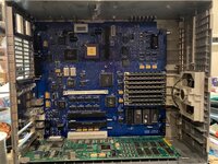
The IIcx in question was actually purchased as a repair project until I noticed the board had layer marks, and to my surprise it was a 4 layer board!

We all know what that means:

24-02-22.JPG

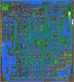
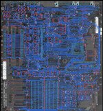
Top layer traces are done, and man this thing has a lot of traces and VIA's!

And a special thanks to @Kai Robinson who managed to figure out how to get sprint to load the board scans which it initially refused to (Turns out Sprint has a size limit when loading colour images which very large boards exceed, converting the image to grayscale avoids this issue)
 

joshc

Well-known member
Ooo is this using the IIcx you bought from me @max1zzz ?

Excited to see this one come together, I didn't keep any IIcx in my collection but it's still nice to see this one getting off the ground.
 

Trash80toHP_Mini

NIGHT STALKER
Dang, didn't come up with one. :(

Nothing there outside of mentioning availability of area for adding thruhloes for a ROM SIMM socket. It would be set to just clear the solder side of the middle NuBus card. Add a jumper to enable/disable chip select on the four traditional ROMs per IIsi.

Socketing the ROMs amounts to the same thing. But switching back and forth between experimental ROM SIMM and stock quartet with jumper on a three pin header setup comes to mind.

Clean ROM SIMMs are readily available as new builds, but discrete sets of four would work just as well.
 
Last edited:

volvo242gt

Well-known member
Dang, didn't come up with one. :(

Nothing there outside of mentioning availability of area for adding thruhloes for a ROM SIMM socket. It would be set to just clear the solder side of the middle NuBus card. Add a jumper to enable/disable chip select on the four traditional ROMs per IIsi.

Socketing the ROMs amounts to the same thing. But switching back and forth between experimental ROM SIMM and stock quartet with jumper on a three pin header setup comes to mind.

Clean ROM SIMMs are readily available as new builds, but discrete sets of four would work just as well.
The IIcx does have a ROM SIMM socket preinstalled. So, that's already there. Installation of a IIfx ROM SIMM into a IIcx results in a slightly slower IIci that has no VampireVideo. Did that back in 2013 when I had a IIcx that wouldn't boot. Chucked the fx SIMM I had into it, and the computer booted up without problems.

Since there is no video port on the cx board, maybe hacking in an AAUI port and ethernet capability would be desirable.
 

max1zzz

Well-known member
Ooo is this using the IIcx you bought from me @max1zzz ?

Excited to see this one come together, I didn't keep any IIcx in my collection but it's still nice to see this one getting off the ground.
Indeed it is!
Nothing there outside of mentioning availability of area for adding thruhloes for a ROM SIMM socket
As @volvo242gt says the IIcx already has the standard 64pin ROM SImm slot
Modifications will be more down the line thing as layouts done in sprint are not really the best for modifying, however once you have a layout in sprint using that to make a schematic in KiCad, Eagle or whatever PCB package you favour is very easy and then you can start making modifications :)
 

max1zzz

Well-known member
Much progress has been made since my last post!

The board was (almost) fully assembled ready for testing at the weekend:
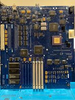
IMG_1984.jpg
(and yes, that board is totally coated in flux so every little bit of crud on my desk sticks to it which is lovely..... this board really needs some quality time in the ultrasonic)

On testing this I got.... Nothing. The PSU didn't even start up (and yes I did remember to fit that missing HC132 before testing :) )
Much probing and staring at the board layout in sprint revealed loads of missing traces a number of which where in the startup circuit (there where also a couple around the RAM address mux's and a few elsewhere)
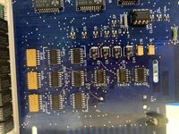
IMG_1988.jpg
This got the board powering on but with no chime and no video, A little bit of probing later and it turns out the ASC wasn't connected to 5V, oops! One bodge wire later and the board was producing beautiful clear.... death chimes.

I spent hours trying to figure this out without being able to find any further issues with the board when I started thinking about my IIx, it's a pretty much identical machine hardware wise and I had a similar issue which after months of troubleshooting turned out to just have a bad ROM, maybe this was the same....

I stuck a ROM Simm socket on the board and chucked a SE/30 ROM in it and.....
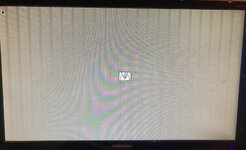
IMG_1985.jpg
More investigation revealed ROM MH at UA2 was bad, one 27C512 later and the board was booting with the onboard ROM :)

This was the point I did something I probably should have done earlier and test fitted the board in the case, whatever I did it just would not lay flat and I just couldn't figure out why......
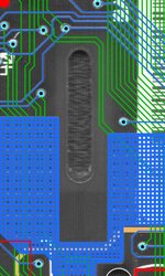
06-04-22.JPG
Ahh yes, it helps if you remember to put all the locking slots in the board!

Never mind, I can vaguely hack a slot out the board
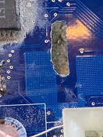
IMG_1990.jpg
And it fits!
IMG_1992.jpg
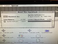
And even boots Mac OS
IMG_1993.jpg
The board is bit of a tight fit in the case so needs to be slimmed down a tad and the latching slots are also a bit short making the speaker quite a tight fit so some adjustments are in order for the next revision

That should have been then end of it for now but just as I was about to go to bed last night I found two odd faults: first off only the left NuBus slot worked, installing the graphics card in either of the other slots gave a gray screen for a second then the computer would hang and installing two cards in any slots gave death chimes. Secondly I found setting the volume level lower than 2 made it lock up and then give death chimes on boot until the PRAM was reset which is a odd fault to say the lest!

The NuBus issue turned out to be that different arrangement's of ground pins are used on each slot to identify them and I had just copied the same arrangement for all 3 slots. a quick bodge wire got a second slot working (getting the third to work would require removing the connector form it which I'm not going to do)

The weird sound issue also had a simple fix: it turns our I had forgot to solder one side of the right sound chip, I'm guessing that when the volume was set to a low level the chip would glitch out and start yanking on the reset line (the machine was not resetting, but this is the only way I can really think of that one of the sound chips could crash the machine) Rectifying this allowed me to set the volume as low as I liked :)

That's it for now :) the board still needs some more testing but It'll probably be a week or two before I get around to finishing it
 

joshc

Well-known member
Wow, lots of troubleshooting you had to do there, impressive you always seem to solve it too. Those are things I would get very stuck with.
 

Trash80toHP_Mini

NIGHT STALKER
Nice! Don't populate the second bank of SIMM slots. With PiHat headers we can test our 72pin SIMM conversion on that lovey bodge wired prototype. :p
 

max1zzz

Well-known member
Board layout, gerbers and scans are now on GitHub:

As with my other designs these are provided under a non-commercial licence but if you are a repairer and want to offer transplant services (or have any other commercial use in mind) please contact me

I will also get a BOM uploaded to github soon, turns out I never transferred it from the original paper copies so i need to dig those out....
 

Phipli

Well-known member
Board layout, gerbers and scans are now on GitHub:

As with my other designs these are provided under a non-commercial licence but if you are a repairer and want to offer transplant services (or have any other commercial use in mind) please contact me

I will also get a BOM uploaded to github soon, turns out I never transferred it from the original paper copies so i need to dig those out....
Thank you so much max1zzz, I have a IIcx to repair at some point and I suspect the layout will help me troubleshoot! The blue board looks amazing. That must have been a huge amount of work. I'm still flabbergasted to see people pull off projects like this.
 
Top