-
Updated 2023-07-12: Hello, Guest! Welcome back, and be sure to check out this follow-up post about our outage a week or so ago.
You are using an out of date browser. It may not display this or other websites correctly.
You should upgrade or use an alternative browser.
You should upgrade or use an alternative browser.
M
max1zzz
Profile posts Latest activity Postings About
-
 robin-foI have a Radius Pivot LC PDS card. How would you clone the main ASIC there? Wouldn‘t it be more feasible to adapt some simple PDS video card logic (maybe even SE/30 internal video bumped to 640x480)?Ccheesestrawsyeah - I have a spare LC PDS graphics card but it looks like it relies on unobtainium chips so it probably wouldn't help you much.
 PowerbaseMan, that's awesome. My ole Iici didn't even turn on last I tried.
 zigzagjoeYeah. I've got a source for the 15ns that's been reliable, but anything faster is impossible to get. I stripped some powermac cache modules when I was experimenting pushing my Diimo and Carrera clones. I did get some 10 or 7ns TAGs from Utsource, but they looked ... manky... so I've not tried to see if they're any good.
 PhipliDon't forget the slot cover holes
 SophieRoseLooks like the inside of my Mega ST lol stack em high
 olePigeonIf you made it a full-size card with pass-through on either end, could you then put two smaller cards on either end?Mmax1zzzSort of, this approach only works because this the accelerator is not really a PDS card, it is just hanging a faster CPU off the bus and the PDS connector happens to convinently have all the needed signals . If you wanted to do the same thing with two PDS cards you would need additional circuitry to handle the card selection.
My end goal here to to integrate the nic onto the accelerator card PhipliCould... I make a minor variation request? To add a small number of extra resistors to enable overclock experiments? I need to check exactly what is needed, but it would be like, 3 resistors and pretty easy to route (between a sig and a plain).
 LaPortaIs there a thread on this?
 CircuitBoredI really, really wish I could justify buying one of these. They're just so cool! CongratulationsCcheesestrawsPhipli has a better eye than me!
 EmmyOcelotCan't wait to see them! This project looks amazing!
 CC_333That's fun! I think at this point, if I want any of these fancy things (286 card, SE/30 accelerator, Xceed greyscale card, etc.) without going broke, it'll have to be a clone.
 micheledipaolaSuper interested! Count me in!
 maceffectsThis is amazing! If you shrink it down with FPGA that will simply be mind blowing!!
 -
Loading…
-
Loading…
-
Loading…

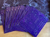
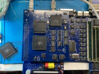
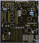

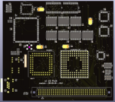
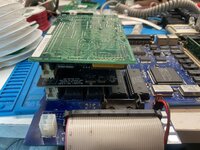
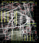
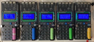
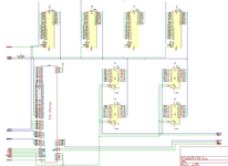
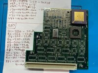
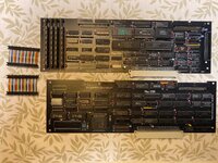

Adding multiple PDS cards gets a bit more complicated as you have to handle card selection, smooshing one card and a accelerator together is much easier as the accelerator is not really a PDS card. Maybe I need to get my hands on one of those crazy expansion chassis's that let you have multiple PDS card sin a LC.....

Reactions: Phipli