• Updated 2023-07-12: Hello, Guest! Welcome back, and be sure to check out this follow-up post about our outage a week or so ago.

MicroQuadra 630

bigmessowires

Well-known member
Hmm, something seems strange to me here. I don't understand the purpose of the pull-up or pull-down resistors in the schematic from post #42. It seems that a simple inverter should be all that's needed. The first link in post #39 shows a solution with a single-transistor RTL inverter and no pull-ups or pull-downs. 


Floofies

Maker of Logos
As you can see, I did build both versions. I built the one with the load resistors because when a Quadra 630 pulls PFW low, it is not low enough to meet the minimum low voltage of the inverter to trigger it, and the time the microcontroller on the LB holds that line low is quite short. Both inverter IC's should behave the exact same without resistors: power-on and no shut down.

The load resistors are present on the Quadra 630 stock PSU as well. That means we are sort of borrowing a bit of the original power control circuit design, to lower the voltage in the same way. PFW is normally 5V until some of it gets dumped into the PSU ground layer by what looks like a diode and resistor. This is why I was seeing such drastic differences in PFW voltage between stock and ATX PSUs.

Looking at the data sheet for the 74HCT04 inverter, the only difference is some clamp diodes which don't help due to how subtly PFW goes low. I suspect that inverter would work for me similarly with the right load resistors. I also suspect other successful conversions using that inverter have different reference voltages coming from the systems they're used in.

 
Last edited by a moderator:

Floofies

Maker of Logos
I used a 6.9KΩ resistor since that's what I had on-hand. Only a 0.1V difference, which is just fine. It still puts it right above the minimum high voltage, and lets the LB pull the voltage down to the maximum low voltage.

With that taken care of, now I can begin work on the new case design. I may make some Photoshop mockups!


Floofies

Maker of Logos
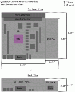
Mapping out my space requirements now:

Q630_Custom_Case_Dimensions.gif

I think I'll have the CF card stick out of the front through a slot, so I can easily pop it into one of my PC's when I need to.

About the CF card... I still can't get mine to work. I am using this adapter: http://r.ebay.com/f9tbJPand this 16GB Sandisk CF card: http://a.co/8MOWfXX

What happens is, OS8 Disk Tools Lite can see partitions and also (I think) create them, but it can't mount any. The adapter and card operate normally on my main PC. I also tried doing the partitioning and added a partition map from a Linux install which is set up for HFS volumes, but that didn't help. I think I may have to switch this card from Removable DIsk mode to Fixed Disk mode, since it implements a different set of ATA commands between those two modes, and perhaps the commands in Removable Disk mode aren't working well with the 630's PATA interface. If I can't switch it, I think I'll try finding an industrial card which comes like that by default.

Worse-case scenario is I might have to shove a laptop hard drive in there, I guess.

 
Last edited by a moderator:

Trash80toHP_Mini

NIGHT STALKER
Sweet, good to see you successfully clearing that hurdle! Can't wait to see simplified docs and to then apply it to the SuperIIsi ATX conversion.

I'm torn on case design choices for a 630/6400 BenchMac build. Leaning toward a tower, because an 80% Q700 build doesn't excite me outside of a slotloader floppy slot tweak for the 6400 version.

The only thing remotely intriguing right now would be a backup home for the 8" 800x600 LCD I've been eyeing.

I'm thinking of angling it in front for a NeoMacintosh Design Language riff 3/4 scale Twiggy Lisa. Maybe 3.5" FDD and SCSI Zip drive behind the cutouts? I've got an internal, but it's not too big a deal to configure an external for internal use here.

_________

|             |    \

|             |      \

|             |       \

|             |___ _\

|             |         |\

|            .|         |  \

|            .|         |   \     

|             | _ __.|__/

|              |   |.

|              |     \___

|_______|_______ \

Dunno, but I do like the shallow depth and the prospect of building in a KVM to use an LCD with other Macs in my collection. A lot depends on depths of the mobo components and ow the line up with the drives. Might need to switch to a larger LCD.


Trash80toHP_Mini

NIGHT STALKER
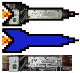
Decided to go with the stock PSU and a LegoMissleCommandMiniTower approach. Has anyone tried to clock the Q630 board past the 40MHz mark with a 40MHz CPU on board?

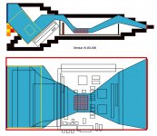
The temptataion to fab a Venturi effect nozzle directiing high velocity air past a heatsink on the Proc from the Q840AV using convection cooling only is too great a challenge to let go.

venturi_principle.gif.b711e97654ae77d24280fd5bdffb5851.gif


Trash80toHP_Mini

NIGHT STALKER
Very rough approximation. I can probably shave some width and height, but size doesn't matter really matter. [:eek:)] ]'>

Q630MCMT.A.00-X.jpg

Now that I see it sideways to match the airflow diagram I can see that the fins may be a step too wide. Maybe I can go a tad taller that way. Dunno, it all boils down to the Lego Grid.

 
Last edited by a moderator:

Floofies

Maker of Logos
Well, let me say this: Having overclocked my 040 to 40Mhz, it has gotten dangerously hot. Burned my finger on the heatsink. I also now regret my choice of hot glue to keep the heatsink in place... it started swimming around on top of the screaming hot thermal paste! I'm planning on jury rigging a 40mm fan on top of the heatsink, but there is a problem with just sticking it on top. Airflow needs to flow up from the bottom side of the case and out through the top, so a fan blowing across the heatsink in the direction of convection will be most optimal, but I'm probably not going to use a nozzle.

Getting the ports of the video-out and Video System tacked onto the back will be an interesting challenge, as they have to reside on the logic board's backplate without being attached to it. It will take a weird arrangement to keep them out of the way, to keep the LB easily removable. 


Trash80toHP_Mini

NIGHT STALKER
I'm ditching the drawer concept entirely, flip top (side panel of Missile) will be flat plexi with the Venturi ductwork attached to it temporarily. I can save a lot of space that way without losing convenient access. I'll likely just be building a butt ugly plexi mockup to test the cooling concept.

Middle little brother, the ME who does server packaging says that once a fan is introduced into a system, convection goes out the window.

If convection cooling works out, I'll pretty up the clear plexi ductwork to install sans cover plate. Filling the rough ducting in with plaster of Paris,rounding everything over to smooth the inside angles into gentle curves would be ideal. Filling, sanding and overcoating the plaster with a high gloss enamel to use the result as a buck for vacuum forming an "inverse bubble canopy" for the Proc and heatsink would be the optimal outcome.

If the Venturi effect doesn't do the trick, I'll just tear it down and fall back on the FauxLisa/6400/G3 BanchMac project.

The cooling air for the proc is pre-heated by the PSU "firebox" of the MacChimneyTower, so there is that little quirk to consider. :-/

 
Last edited by a moderator:

Floofies

Maker of Logos
I have ordered this industrial CF card: http://a.co/dmmS3nI

I hope it works. If it doesn't, I'll have to stick a (potentially noisy) laptop hard drive in there, or worse if that doesn't work either.


Floofies

Maker of Logos
We have liftoff! The machine booted Mac OS 7.6.1 off the industrial-grade 8GB Transcend TS8GCF170 perfectly, the first time too! I REALLY outdid myself and jackhammered the partitions onto it from my period-correct WDC drive. I used GParted and a few other Linux-based tools to get the job done, but I don't think the Apple Partition Map liked some of the things I did, since one of the FAT partitions is now invisible... that can be fixed later; for now, let's crack open a 6 pack and bask in the success!

Now the only remaining item to get done is the micro vertical case, made possible by everything else in this thread so far!

Jt, I'll be posting some Q630-specific schematics for my adapter design soon, as well as an updated ("correct" version, as the other one is barely accurate!) schematic for the Q630's Dyna-Comp PSU. I'll include a parts list so you can hack your own together all speedy-like.  ;D


Trash80toHP_Mini

NIGHT STALKER
Sorry for that silly tangent, how's your design coming along? The ATX conversion is of special interest to me for several hacks including at least two based on the Q630 MedusaMess.

The worst of the ATX PSU conversions places a small unit inside the stock sheet metal enclosure of the IIsi PSU. I think I'll hunt down the drawing I did for that PCB breakout board. If you could mark it up to include your electronics, we could go from there right into a SEEED format universal ATX conversion board spec. for 68K.

Clipping connectors and soldering the wires from both ends to a PCB appeals to me a lot more than the shrink wrap approach, especially with your 68K  startup/shutdown electronics involved.

Developing a board for inside the least common denominator 0f the B&W G3 -> MDD sheet metal series dimensions appeals to me as well.


Floofies

Maker of Logos
I haven't put together the mockup yet. My resources are bit limited and I'm currently job hunting, too; not a lot of time to go nuts with a hacksaw.

Here's a CORRECT diagram for the Q630's PSU. The other one on this thread has some errors in it due to skipping pins on the edge connector, whoops!
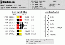
Q630_PSU.gif

As for the ATX adapter, I'm working on an easy to understand diagram now. One thing I'm wondering about is why the /PFW Ground load resistor value is so different between Dan's design and my own. His calls for a 47KΩ resistor, but I could only get the Q630 fully working by using something closer to the 7KΩ range... All of that makes me think there might be some variances in how /PFW works on some of these old machines, so it very well could end up being a "YMMV" situation with that load resistor's value.

For now, based on all my poking and prodding, the /PFW line on the Q630 is basically a direct feed from the +5V line on the main supply plug. I think it should work consistently with a 7KΩ resistor unless you have leaky caps.

Also, here's some messy in-progress destruction of that edge connector. I'm straight up ripping the 50-pin SCSI off completely, and I might repurpose the CD audio cable for a neat audio-in port mod (depending on how it works, expect some experiments later on with that). Other cables will probably be shortened considerably.
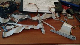
IMG_20170720_122415089.jpg

 
Last edited by a moderator:

Trash80toHP_Mini

NIGHT STALKER
Yep, figured the beheading of Medusa would be coming up soon. [}:)] ]'>

PCB could have a row of resistors wired in parallel with a header/jumper setup. If the first value works, cool. If not, just keep adding different values until the jumper finally connects to one that works reliably.  Then add a couple more to extend the range of choices just in case.

Good hunting, my friend.


Floofies

Maker of Logos
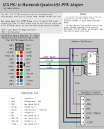
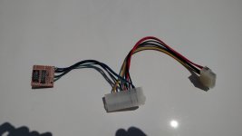
Okay, I think this illustrates all the non-obvious stuff. The Q630 main supply plug is very straightforward so I did not document those connections, just the 6-Position Auxiliary cable. Of course, if you decide to use 6-Pin IDC instead of the socket/plug the Q630 comes with (I recommend it, the thing sucks) you will have to map those pins yourself as needed. On another note, I just got hired for a System Administrator position at Turner Broadcasting! I will soon have some disposable income to throw at this project! Woot!

Let me know if any of this makes sense!

gallery_4627_236_4914.gif

A shot of the real deal. You can remove the pins of the ATX plugs with safety pins or staples.

IMG_20170725_125131019.jpg
 
 
Parts List:

  • 1x 20 or 24 Pin ATX Extender; Like this one: http://a.co/9OoyccA
  • 1x 14-Pin Molex MiniFit Jr (Can be taken from a Q630 PSU or hacked from a larger MiniFit Jr connector, too)
  • 1x 74LS04 Integrated Circuit
  • 1x Prototyping Perfboard
  • 1x 10KΩ Resistor
  • 1x 7KΩ Resistor
Optional, but makes things easier:

  • 1x 6-Pin IDC, Male, Thru-hole pins
  • 1x 6-Pin IDC, Female, Cable Snap-on assembly
 
Last edited by a moderator:

Floofies

Maker of Logos
Hm, whoops. Made a typo in the notes and put "-12V Line" where I meant to put "+12V Line". Would be nice to have some way to swap out the attachment.


Cory5412

Daring Pioneer of the Future
Staff member
Eventually, that change is planned. In the mean time, PM myself, ulterior, bunsen, and/or gorgonops and we should be able to put the updated image in your post.


Cory5412

Daring Pioneer of the Future
Staff member
I missed the new job comment, congratulations!

Also, I updated the picture, and I think I got it right.

 
Top