• Updated 2023-07-12: Hello, Guest! Welcome back, and be sure to check out this follow-up post about our outage a week or so ago.

MicroQuadra 630

Floofies

Maker of Logos
She' s alive! She's ALIVE!
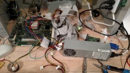
IMG_20170107_195017948.jpg

IMG_20170107_195124590.jpg

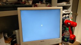
I wired up a TI 74HCT04 Inverter with the /PFW and +5VDC pins on the 6-pin header, connecting the output pin to the PS_ON# pin in the ATX PSU; it fired right up and I yelled! Pretty sure I scared the neighbors.
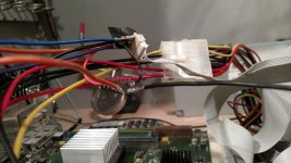
IMG_20170107_195044339.jpg

There is one issue, though. /PFW is being held abnormally high, and won't go low, or won't go low long enough for my meter to see it. This prevents the PSU from turning off, and just resets the machine when the programmer's switch is pressed. Shorting /PFW to ground manually does the job, thankfully, so I know it's functionally able to turn the PSU off. Kind if frustratng, I wonder what the issue is... I suppose it's possible the /PFW line gets pulled lower, but not to 0V, maybe keeping the inverter stuck.

 
Last edited by a moderator:

Trash80toHP_Mini

NIGHT STALKER
She' s alive! She's ALIVE!
Mazel Tov! That's great stuff you're coming up with in the process.  :cool:

I'm really looking forward to your final report, having the electrical characteristics of the conversion mapped out in addition to the usual basic wiring diagram will the the first I've seen for any ATX conversion. You're saving me quite a bit of the kind of work I enjoy the least. I've got three 6500 based projects alone on the backburner awaiting ATX PSU conversions as well as others like the SuperIIsi which needs a lot of beef packed into its cute little sheet metal box.

 
Last edited by a moderator:

Floofies

Maker of Logos
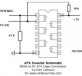
I muddled a bit on why it wouldn't power off, and I realized I needed to make other connections. That inverter isn't monodirectional... The /PFW line is being held high by the inverter after it initially goes high at boot, so there needs to be a resistor to GND so both /PFW and the pin on the inverter can go low properly. Since this type of conversion works on ANY Mac with a /PFW line, there is a HUGE amount of resources and research already done, so I found this:

http://www.xlr8yourmac.com/systems/MacinPC_ATX_case/pages/ATX_Power_Adapter.htm

ATX_Power_Adapter.jpg

This here schematic is right on the money! Except it has 2 more connections made.

A 10kΩ resistor between the PS_ON# and +5VDC lines, then a 47kΩ resistor between the /PFW and GND lines. That connection on /PFW I figured I'd need, but I had no idea what the specifics should be. That resistor on PS_ON# definitely isn't something I thought I needed, but I guess it's the exact inverse of the issue with /PFW; PS_ON# needs to go high but  gets stuck low.

Now that I know I can use the ATX PSU, I'll start creating the custom case.

 
Last edited by a moderator:

joethezombie

Well-known member
Excellent detective work. Very nice to have all this rolled into a single thread! I'm patiently waiting to see your case design.


max1zzz

Well-known member
At risk of takeing this thread on a slight tangent, This has got me thinking about my failed attempt to install a ATX PSU in my 8500.

I tried to do this with a simple NPN transistor (between PS_ON on the PSU with PFW on the base of the transistor), this works - for about 5 seconds, after which the psu shuts off. I could never figure out why this happens. Can anyone give me a incite in to why this is the case, i'm sure i'm missing something really obvious but I just cant see it....

Anyhow, I have ordered some 74ls04's to give it a try using them


Floofies

Maker of Logos
It could be a few things, but I really don't know much about the 8500. If it's anything like the Q630, then If /PFW line voltage goes too high (Above 6V) or too low (Below 3V), the system shuts down.

Assuming you wired it correctly (IE: /PFW to Base, GND to Emitter, and PS_ON# to Collector), the problem was probably the fact that /PFW would be partially or fully shorting to ground, lowering it past 3V after the initial 5V-6V capacitor charge dissipates. In the Q630, /PFW naturally sits at around +3.4VDC, so that's not a lot of room for a voltage drop. I'd try to remedy that with a resistor between /PFW and Base, as you only need a tiny amount of voltage to trigger the transistor.

In other news, that CF card adapter I initially bought really is a wacky thing. OS8 Disk Tools can see the partitions just fine, and can even start a disk check, but I still can't mount or initialize anything. The recommended adapter is in the mail. Also, my DB25 connectors never came, and were last seen in Shenzhen, China, on December 8'th... Guess I'll be waiting awhile to proceed with the Floppy/CF parts of the project. Stay tuned for a swank case mockup. :)

 
Last edited by a moderator:

Floofies

Maker of Logos
Ugh! How frustrating! I still can't get it to shut down, even with those resistors in place. I think I need a diode between /PFW and the pin on the inverter, because I am pretty sure +5VSB (Vcc) is feeding back into /PFW and making the system stay on, even with the resistor in place. Maybe it's something weird with this type of inverter? Maybe I should use one of the regular +5VDC lines instead of +5VSB?

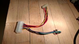
Here's the completed adapter:

IMG_20170111_175727413_HDR.jpg

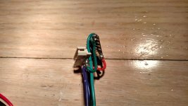
And the 6-Pin header with inverter attached:

IMG_20170111_175803271_HDR.jpg

I checked the wiring a ton and tested a ton with the voltmeter, and I'm just seeing the same voltages/behavior as if the resistors weren't there. Any ideas?

 
Last edited by a moderator:

Floofies

Maker of Logos
http://www.xlr8yourmac.com/systems/ATX_PS_in_8600_9600/ATX_supply_in_8600_9600.html

Inverting the Power-on line

I did need an inverter circuit for the Power-on line from the 8600 motherboard. This line goes high when the power button is pushed, and it needs to go low for the Power-on line in the ATX supply. Dan Calhoun used a 74LS04 IC to do this. [Previous article - see Related Links below-Mike] I realized that if I used a 74HCT04, I wouldn't need any resistors or other parts; just the IC. If you use the LS version or any non-CMOS version of the 7404, you will need the resistors Dan shows in his circuit.
Huh. So I don't need the resistors. Now I'm confused...


Floofies

Maker of Logos
I broke my hand in January and have since been distracted by other things, but I assure you this is still continuing.

I'd very much like to get shutdown working, so I'll be poking at this a bit more soon. So far I have two strong theories as to why it won't shut down.

One is the clamping diodes in the inverter have some specific tolerances either from stock, or their automatic adjustment, which don't jive with the logical low of the PFW line. The other theory is I have failed to fully connect the header, (There are 2 pins I could not map to anything) and the PFW requires one pin to ground in order to drop to logical low.

In any event, the inverter isn't flipping back around so that PFW shorts to ground and PS_ON shorts to the 5VSB line. If it turns out to be more trouble than it's worth, I might just ditch the inverter and use a transistor, since I can more finely tune which volages do what.


Gorgonops

Moderator
Staff member
Years ago I did a tray-loader iMac ATX conversion and went with the transistor-based circuit, and I'll note offhand that I had a lot of trouble with it "bouncing" right back on again on shutdown with the majority of ATX supplies I tried it with. It does seem to take a bit of black magic to tune it.


Floofies

Maker of Logos
I'll be trying a 74LS04 before the transistor, with the resistors, since I can similarly tune the voltages by changing the values of the resistors. If that still doesn't work, I doubt the transistor would either.

 
Last edited by a moderator:

Themk

Well-known member
This is awesome. Keep up the good work! [:)] ]'>

I must say I love my 630. It is a fast little box. I assume you have done the 40MHz un-crippling mod?

 
Last edited by a moderator:

Floofies

Maker of Logos
Yes, it has the resistor mod to run the CPU at 40MHz, hence the heatsink. That will be an interesting thing to cope with once I cram it into a tiny case!

While I'm on that topic, I decided to make room for the entire Apple Video System, since I don't think it would take up much more space. I'll be modifying the 630's LB-attached metal backplate anyways, which will let me add some holes for those ports, and the standard monitor-out board port. This thing is going to be a SICK micro HTPC by the time it's done.

I am moving forward with the next revision of the adapter, crossing my fingers so this one works! Ordered some 6-pin IDC connectors, some prototyping perf-boards, and of course the 74LS04's. I wanted the IDC connectors because the 6-pin header the 630 has is just nasty now, I messed it up with all my experiments... so now it has missing pins, partially melted, and I couldn't find what model it was to order more. I'll just snap on one of the IDC connectors and bypass the stock one entirely. :)

 
Last edited by a moderator:

Floofies

Maker of Logos
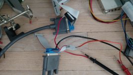
Putting together the external floppy interface while I wait for more parts to arrive. Now taking bets on whether or not it will work with such a long cable...

IMG_20170610_180701759.jpg

 
Last edited by a moderator:

Themk

Well-known member
Now taking bets on whether or not it will work with such a long cable...
On the Apple IIgs, the floppy drive must be plugged into the external port. Also, on the IIgs you daisy chain the drives. My floppy drive daisy chain works very reliably even at the end of the chain. With the circuitry on the motherboard of the IIgs, the cables themselves, as well as the wiring inside of the drives, this turns out to be fairly long. I think you will be fine here.

 
Last edited by a moderator:

Floofies

Maker of Logos
Floppy works just fine! :)

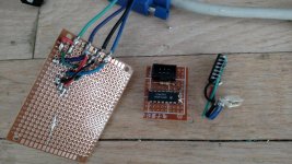
The power adapters, not so much... Here's the three I have been able to make so far:

IMG_20170625_184555239.jpg

I made two revisions based on Dan Calhoun's 74LS04 adapter for the 8500 series, and neither worked. Very odd behavior, as both revisions cause the PSU to not power on... until I unplug the 6-pin header altogether, at which point the ATX PSU turns itself on and the Mac boots all the way up!

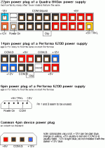
There is still hope though. I found out the Quadra 630 PSU is 100% interchangeable with the Power Mac 6x00 series, meaning any ATX conversions done on those machines should work the exact same for the Quadra 630! I was able to find this handy image:

plugs.gif

It seems to show both the main power connector AND 6-pin header, further confirming my own findings! I am so close, l can hear the "Bong!" already!

 
Last edited by a moderator:

Floofies

Maker of Logos
Well this is an interesting bug. The two 74LS04 versions have some sort of short-to-ground issue.

As long as the Mac's 6-Pin header is connected, the +5VSB (Trickle voltage) line shorts to ground every other second, and never goes above 0.2VDC. That supply then goes down to 0V and unshorts from ground, then starts powering back up, and then it shorts again, on a cycle. My volt meter's continuity test (Between +5VSB and Ground) beeps very consistently, on time, about once a second. The 74LS04 loses power because of this, which causes the Mac to be un-bootable. Because this only happens when the Mac's 6-Pin header is connected to the adapter, that certainly narrows it down some.

When the 6-Pin header is unplugged, the 74LS04 flips the PS_ON line low (shorting it to ground) and the PSU just turns on by itself.  :scrambled:

 
Last edited by a moderator:

Floofies

Maker of Logos
I found a bug in my notes and fixed it, turns out I got one of the NC pins (which turns out to be connected to Gound on the LB, but to nothing on the stock PSU! Ugh!) mixed up with the 5VSB line. Once repaired, it started behaving like revision 1, so I took that as a sign to play with some resistors!

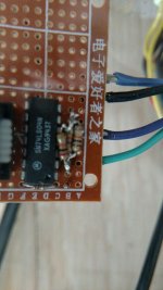
After fiddling with the resistors, it fully works now! Power-on and shutdown! Take a gander at THIS monstrosity! :D

photo_2017-06-27_14-51-17.jpg

Those are 3 resistors in parallel from the PFW line to Ground: 47KΩ, 20KΩ, and 10KΩ. Combined, they drop the PFW idle voltage down from 4.5VDC to 2.7VDC. This is below the stock 3.4VDC I was seeing, but at that voltage the drop-out was too shallow to flip the inverter back around.

I piled those resistors on because I don't have a breadboard, and it's much easier to add than to replace on that tiny perf board. I figured I should be able to calculate the single resistance value that does the same thing. According to an online calculator I used, it is around 5.8KΩ


IlikeTech

Well-known member
I would try replacing those resistors with a zener diode to regulate voltage in some way. I haven't looked closely, but those resistors pobably get hot after a while.

 
Top