• Updated 2023-07-12: Hello, Guest! Welcome back, and be sure to check out this follow-up post about our outage a week or so ago.

MicroQuadra 630

Trash80toHP_Mini

NIGHT STALKER
Once you've built your own or matched an adapter to the native resolution of your display, there's no need for tweaking. If tweaking might be necessary, the easiest thing would be to place the VGA port vertically on the very edge of your case and use a hole saw in just the right spot for access to the "Liberty" dial. :quadra:


Compgeke

Well-known member
For old systems a consumer card should work fine. The old mac os versions arent constantly writing to the disk and the files themselves are fairly small. I've has a few in cameras that had hundreds of full capacity writes and never dies.


Floofies

Maker of Logos
Thanks, it's certainly motivating to hear that.

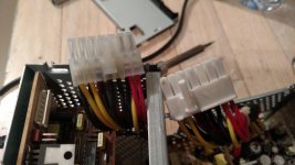
The ATX PSU adapter is coming together now... I hacked apart one of the Q630 PSU's for the main socket, and I'll continue to use that PSU to figure out what else goes over that other small cable. I think I'll desolder the socket for it, and break out the conductors so I can test with it powered on. I'll need to desolder that connector anyways to complete the adapter.

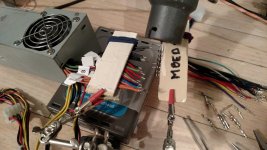
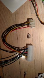
Here's the ATX PSU. I trimmed the long cable back and I'm now rebuilding the plug, converting it from 20-pin to 24-pin in the process.

IMG_20161128_201029030.jpgIMG_20161128_160149572.jpg


Floofies

Maker of Logos
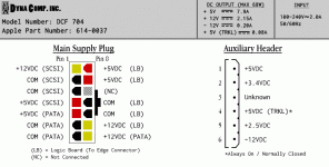
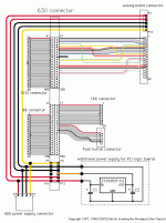
Here are my findings! I made a little pinout guide, but it's not finished! I'm going to need some advice on how to proceed, actually.

Q630_PSU.gif

Some things to note about that 6-pin header:

  • Shorting Pin 2 to +5VDC (TRKL) while system is OFF = system power ON.
  • Shorting Pin 2 to +5VDC (TRKL) while system is ON = system power OFF.
  • Shorting Pin 2 to Ground while system is ON = system power OFF.
  • Shorting Pin 5 to +5VDC (TRKL while system is ON = system power OFF.
  • Shorting Pin 5 to Ground while system is ON = No effect.
I do not understand these results 100%, and as you can see there is one pin I could not identify.

I believe it is obvious that Pin 2 is the power-on circuit, however I am not sure I understand how the system powers off. The only documentation I can find relates to the Macintosh II. Are there any Powermacs/Other Macs that use the same or similar PSU? Maybe they will have the documentation I need?

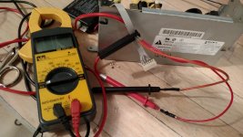
Here's my janky-looking test port.

IMG_20161129_184744190.jpg

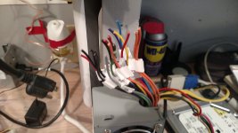
I also custom made a Q630-compatible power plug out of a 20-Pin ATX plug, apparently they are physically compatible if you snip off an end.

IMG_20161129_171745988.jpg

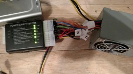
Of course, had to test the ATX PSU after mutilating it! :) It still works.

IMG_20161129_160855387.jpg


Bunsen

Admin-Witchfinder-General
Yeah, there's no need for industrial-grade flash on an OS that doesn't use a swap file.

Have you checked the dev notes for the 630 to see if that power connector is documented?

 
Last edited by a moderator:

Trash80toHP_Mini

NIGHT STALKER
DevNote usually doesn't get into that low level type of hardware IIRC, neither does ServiceSource other than plug and play of undocumented system components. PaperDocs like GttMFH2e never did either AFAIK.

Check out the Power Color Classic project. There was a graphic I called (dunno about others) the "frogeye diagram" that had pinouts for adapting the CC Plug to 630/6360/6400 plug/cable/harness which might to tell you what you need to know. The link there is 404, but maybe someone has a copy on hand? IIRC it being a harness<->harness hack, but buzzing connections should provide the values you need.

 
Last edited by a moderator:

Floofies

Maker of Logos
Trash80, I did find the link (http://member.nifty.ne.jp/frogeye/connector.html#diagram) but it denies all bot access due to it's robots.txt, which means it was not archived like the many other links on that page... How unfortunate. I also found your old thinkclassic posts from 2014, and other relevant 68kmla posts from 2012. It looks like many people have needed this document, and it hasn't been seen since at least 2012.

That said, I am still piecing this stuff together with or without the document, and I'll gladly document everything I find out. While browsing those old posts, I found references to "ADB Power Supply and Power-Off Command" lines, which helps explain Pin 1 and maybe Pin 5. More updates to come as I continue to poke the living hell out of the Q630 PSU!

 
Last edited by a moderator:

Trash80toHP_Mini

NIGHT STALKER
I didn't find the frogeye diagram on the NetBook, but now that I've spent the day playing here, I'll fire up a couple of the Illustrator workstations. I'm positive I've got it archived on disk  .  .  .  somewhere. ::)

edit: it's just Trash or jt (lower case)

 
Last edited by a moderator:

Floofies

Maker of Logos
Thanks for the effort there, jt, trying to map out this 6-Pin header is nothing but headaches. I found out that Pin 1, the one I said had +5VDC coming over it, actually has no voltage whatsoever; I just put my test lead one pin over by mistake. I decided to find out where the ADB got it's power just to make sure, and it's just the +5VDC from the main power connector.

However, that little mistake lead to me finding out what happens when you press the programmer's switch, as that +5VDC line actually went to the video-out board! When the button is pressed, it directly shorts a logical +4.9VDC to ground from a different circuit, tripping something in a little microcontroller, which then in turn temporarily shorts +5VDC (TRKL) to Pin 2, which levels out at +3.4VDC as the PSU powers up. If that +3.4VDC goes any higher or lower, the PSU shuts off. I really don't understand why, though. Shorting Pin 5 to +5VDC also shuts the PSU off, so I assumed that was the power off circuit, but maybe the shutoff is only a side effect? I don't have any way of knowing for sure, myself.

I would hate to have to deal with any kind of digital signal on the power circuit...

 
Last edited by a moderator:

Trash80toHP_Mini

NIGHT STALKER
I beat up the image bushes on Google for a few minutes. Didn't find it, but found the preview of a pic posted here (lost in the great pixel robbery) about the 580<->630 harness adaptation. CC<->6360/6500 harness was similar. But ISTR that it documented the power plug.

4HQWNX.png.76c05e07ae1d96073fda6bcbe273a45d.png


Mods, is there any way to just dump all the lost pixels into one directory we can rummage through in search of lost treasures?


Floofies

Maker of Logos
I found it using Google Image search and your preview!

http://graph.darren-criss.org/2016/01/25/1996-camaro-wiring-diagram-l-f9490e3cf502c93c.gif

Quadra630Harness.gif

I don't see any information about that 6-pin header though, just how to wire it up to the 580 analog board.  :(

Maybe I can find documentation on the 580 analog board, then? If I can see what those pins are for on that analog board, I could correlate them with the conductors from the Q630.

In the very least, it looks like they neglected to use one of the conductors, so now I know one is pretty much useless.

 
Last edited by a moderator:

Trash80toHP_Mini

NIGHT STALKER
At least that one's now backed up. I think that may be an alternate version of the original detailing the full harness/connector, not just the 3V fix for the 6360/6400 PCI implementation. This one's pretty off point for your needs, but good to have anyway.

Stuart Bell, where are you?

edit: mineral, are you still lurking here?

 
Last edited by a moderator:

Floofies

Maker of Logos
Huh. The two +5VDC lines to the LB aren't actually separate 5V lines... they are 100% connected to the same circuit both on the PSU and on the LB; in other words it is not 10V, but actually 5V spread out over two wires. (By the way, does anyone know how I can clearly notate that in the diagram?) Is there any reason in particular it may have been put together that way? If there isn't a good reason, I'm just going to use one of those conductors on the adapter. At this point, it's time for some teeth-gritting experiments which involve possibly frying the LB... for science!

Moving along: a new CF card is in the mail, soon to be followed by another adapter if I can't get the Startech/Syba one to work. I'm hoping I can mess with it enough/modify it, because I'm getting awfully close to the end of my budget.

I have some female DB25-IDC connectors in the mail as well. That will allow me to crimp right onto the floppy drive cable, converting it to DB25, and then back again in the floppy's enclosure. I can think of a few reasons this may not work. but it's cool enough to try!

 
Last edited by a moderator:

Trash80toHP_Mini

NIGHT STALKER
From what I recall, you can't convert 5V to 10V without from a PSU having just one rail(?) you need a transformer. The two 5V lines are separated coming from the AB, might the peripheral power line have less "conditioning" than the LB line? Maybe check the AB end to see if there's a difference after all.

Following this thread with interest, one of my hacks involves running a 6500 board in a Classic using a very small ATX PSU.


Floofies

Maker of Logos
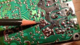
Jt, as far as I can tell, the conductors on the LB go into the exact same 5V supply layer in the PCB. 100% the same circuit on both ends. I also tested directly from the 5V pin on the ADB socket. I went as far as ripping one of the PSU's apart. Here's where all the 5V lines are coming from, one big glob:

IMG_20161206_115428368.jpg

And the adapter... Yes, that is all the LB needs for power!

IMG_20161206_121915887.jpg

 
Last edited by a moderator:

Brett B.

Well-known member
For what it's worth, I used an IDE->CF adapter and a normal 256MB CF card for a PC that I built.  It was running PFSense and served as my router and firewall for at least a year.  It ran 24/7 and I had the traffic logs recording data the whole time.

I did end up taking it out of service because the CF card died but it was a good experiment for me to see how long they can last.  I'm not sure how much data was actually being written to the card and how much was stored in RAM, but in any case, I was very happy with the results.  CF cards are cheap and it would be very easy to image the card and simply replace it if/when it goes TU.


Floofies

Maker of Logos
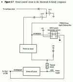
Making some progress in my research about how the Q630 controls power. There is a Power IC on the board which talks to the CPU, which makes logical voltage changes on the 6-pin header. I knew that much just by looking at the board, but not the specifics. Now that I've done some reading, I think the power control scheme may be similar to the early Macintosh II family, as it appears to behave almost exactly like it.
 
All of the following Mac II information closely matches what I see in the Quadra 630, and confirms the findings of my experiments:
 

... when the computer is off, the /POWERON signal is held high by the same battery that runs the real-time clock. When you press the power-on switch on the ADB keyboard, the IPOWERON signal is shorted to ground and pulled low. When /POWERON goes low, the power-on circuit connects the battery to the /PFW line. A voltage from +3 V to +6.5 V on the /PFW line causes the power supply to tum itself on. Once the power supply is on, +5 V from the power supply holds the /PFW signal high, keeping the power supply on.
I must say I am feeling very confident now! I will proceed with some more experiments (AKA shorting random wires :lol: ) involving the ATX PSU. Since ATX PSU's power on by shorting PS_ON# to ground, which is basically the opposite of what the Q630 does, I will have to make some sort of hardware hack for this.

The circuitry may not be a 100% match, but it functions the same:

Macintosh2_Power_Circuit.gif

 
Last edited by a moderator:

Floofies

Maker of Logos
OK, folks, this looks very straightforward now that I know what I'm looking at. Guides already exist for sticking ATX PSU's inside /PFW-enabled Macs, so my investigation and experimentation has come to a close. I will still post an updated pinout guide for the Dyna-Comp PSU later.

All I need to do is invert the /PFW line and connect it to PS_ON#, which can do with a CMOS 74HCT04.

http://www.radiomods.co.nz/imactoatxconversion/

http://www.applefritter.com/node/6429

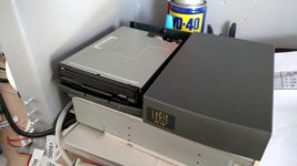
In other news, I found a possible case for the floppy drive. It's the LaCie Joule HD 730 case I had gutted for parts to make the CD-ROM enclosure. Two of the screwholes line up perfectly, so all that needs to be done is a hacksaw job on the front.

photo_2016-12-26_13-12-15.jpg

 
Last edited by a moderator:
Top