• Updated 2023-07-12: Hello, Guest! Welcome back, and be sure to check out this follow-up post about our outage a week or so ago.

1400 Hinge Shim Insert Shim Tutorial

LaPorta

Well-known member
First and foremost:

Many thanks to @AEChadwick for making the hinge fix shim in the first place. There is no way in creation I could have made anything as good as this, or as creative.
Many thanks to @BinaryGrind for printing me a few of these, so that I could go through the process...as well as repair my 1400 back to working condition.

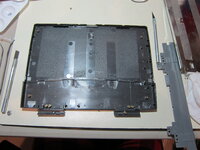
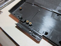
A few months ago, my 1400s clutch standoffs finally gave out, and I had no choice but to do this. Different than most, I did this repair on another 1400 screen back plate that I got a while back that has no hinge cracking at all. This way, my hope is that it won't give out for a very long time, as well as look good cosmetically on the outside.

The goal here is to document that process that I took, along with pitfalls, so that others may feel more comfortable doing so.
 

LaPorta

Well-known member
Here is the piece that I started with. You can see that the bosses were cracking off anyway, so I wasn't sacrificing a "good" one. There was no crack in the actual corner, however, as you can see.
 

Attachments

  • IMG_7068.JPG
    IMG_7068.JPG
    2.1 MB · Views: 4
  • IMG_7069.JPG
    IMG_7069.JPG
    2 MB · Views: 4

LaPorta

Well-known member
So, I proceeded to use my flat xacto blade to chop up the bosses as I went.

IMG_7070.JPG


Also note: the lower, hinge cover boss is SMALLER than the two upper ones. You don't want to confuse these as you go along. I also used a silver marker to mark the location of the holes prior to removing them, as you can see in the photos.

IMG_7071.JPG
 

LaPorta

Well-known member
Test-fitting then proceeded. In hindsight, it didn't fit quite as nicely as it should have. It appears it was offset my a mm or two towards the top of the display housing, but there wasn't much I could do about that since the piece is indexed to thee three-leg towers that the Reed switch sits on top of. You can't get rid of those.

IMG_7073.JPG

The holes were a little smaller than the bosses, so I did some filing until they were just large enough for the bottom to fit into the holes.

**Also take note: the larger two upper bosses are the exact same height as the plastic shim, but the single, lower ones are lot as long as the plastic. Therefore, make sure that you only get them flush to the surface of the shim, not push it all the way down into it. I have included pictures of the bosses next to the shim for height comparison to illustrate.

IMG_7074.JPG
IMG_7075.JPG
IMG_7077.JPG
 

LaPorta

Well-known member
Next, I used the technique mentioned by @MacUp72 : I heated up the bosses and inserted them into the plastic. Unlike his method of heating them up and then pressing, I simply kept my iron inside them and pushed them in with the iron until they were flush with the surface. I used 550 degrees F, lower than my usual 850 for soldering. I then traced an outline with black magic marker so I would know where to put the glue within bounds. The glue used was Testors liquid cement. Despite the tubes looking similar, apparently glue from the same line contains different compounds. It comes in a little liquid despensing squeeze bottle: you can get it at any hobby store. It contains: petroleum distillates, butyl acetate, and ethyl benzene (among other things, I am sure). It works by dissolving the plastic parts together...a sort of plastic weld. It is not like CA-based superglues that simply form a bond themselves. I ran the glue in a crosshatch pattern up and down inside the area I marked. Once the shim was fully in position, I clamped it using wood on the upper and lower surfaces. Once the edges were clamped flush, I also ran a ring of the glue around the edges.

IMG_7078.JPG

IMG_7080.JPG

IMG_7081.JPG
 

LaPorta

Well-known member
After an overnight pause, the final result was glued in nice and secure.

IMG_7082.JPG

Next, I checked the fitment of the metal shield, and determined where I needed to cut. I know some have sliced off the entire bottom half, but I wanted to keep as much of it as I could. I marked off those areas with magic marker, and used some heavy duty metal snips. then test fit it in place.

IMG_7083.JPG

IMG_7085.JPG
 

LaPorta

Well-known member
Next came transferring over the clutches. This was, as you can imagine, the trickiest part, as they have to line up almost exactly. I first placed both panels side-by-side to make sure I transferred everything over in a 1:1 fashion.

IMG_7087.JPG

This was the trickiest part. I found out, after laying the clutches down, that the holes did not line up and the clutches did not lay flat. What to do? Well, I realized that what I was ultimately wanting to do was get the clutch hinge parts lined up in the outer part of the plastic housing. So, in the next photo, getting the clutch to line up and lay flat within the RED encircled area was the key to making it work properly. Therefore, I kept that part of the clutch lined up, and then I inserted my hot soldering iron into the bosses through the clutch holes, and slowly dragging the bosses underneath until they aligned exactly with the holes. Once all bosses were aligned properly, I then checked to see if the clutches were exactly flat with the underlying case. If they were not (which was the case slightly with one side), I applied the soldering iron directly to the clutch, helping to soften the plastic directly surrounding it. I then used the eraser tip of a pencil to the clutch to slightly recess it into the plastic to make it all line up. Sorry I don't have action shots; I only h ad one chance at it! The last photo also shows what it should look like when the clutch is lined up properly: flush with the plastic cover tab, and not raised above it.

IMG_7088.jpg
IMG_7092.JPG
IMG_7093.JPG
 

LaPorta

Well-known member
After this, I installed the inverter board and reed switch. Next came test fitting the LCD.

IMG_7095.JPG
 

LaPorta

Well-known member
The fit of the cable on the left was too tight: the shim pushed up the cable just enough to make the front bezel protrude forward when reassembled. I then used a flat soldering tip to melt down the plastic to create more of a "cavern" for the cable to reside in. I don't know if this was due to the slight offset I experienced in the shim's printing, or if it is just the design. Just know that if it happens to you, you can melt some of it away to create more space.

IMG_7096.JPG
IMG_7097.JPG


With this done, the cable had just enough room to be relatively flush with the LCD frame:

IMG_7098.JPG
 

LaPorta

Well-known member
I was then able to test fit the front bezel, insert the screws, and fire up the machine to test the screen:

IMG_7099.JPG

There is a imperceptible bulge on the left where the cable likely had just a tad less room than it needed...but that is not apparent at all from the front, and it has absolutely no impact on the machine closing or not. It opens and closes like brand new, and I could not be happier.

IMG_7104.JPG
 

BinaryGrind

Well-known member
Thanks for the excellent write up. I imagine the shim/fix should hold up quite well. That said, thanks to your fantastic pictures/walk-through I can spot a few points that could be improved on the shim (eg. the edge you melted for cable routing) and still have it be as strong. When I get a chance I'll see if I can make those changes.

That all said, if anyone else needs a shim to fix up their 1400 and can't 3dprint it themselves, toss me a DM, I'm happy to oblige.
 

LaPorta

Well-known member
Thank you for that. I was hoping that things could be optimized as a result of my experience!
 

AEChadwick

Well-known member
this is fantastic—i couldn't have commissioned better work; i'm thrilled to be part of the process. thank you for giving this to the community. (@BinaryGrind please share your remix!)
 

3lectr1cPPC

Well-known member
Great guide. Interesting to see that you also had alignment issues! I wonder if the STL needs to be corrected.
 

AEChadwick

Well-known member
i have installed this shim into three PowerBook 1400cs. I don't doubt it could use some finesse, a half-a-millimeter here and there that i was too deep in to notice, "meh i'll just push a little...”; i appreciate the objective assessment. If someone can adjust the STL--and maybe someone install the revision, the ultimate test--i will gladly share that version. I would revise it myself... but i don't have another 1400 to study!
 
Top