• Updated 2023-07-12: Hello, Guest! Welcome back, and be sure to check out this follow-up post about our outage a week or so ago.

PowerBook 1400c/166 restoration/combination thread

3lectr1cPPC

Well-known member
Currently I'm in the process of doing a lot of PowerBook 1400 repairs. Got a couple units at the recent swap meet - a 117MHz parts unit with a bad screen, and a 166MHz working unit with poor cosmetics. Here's a breakdown of what I'm going to be doing to make the most out of the parts I have:

As they currently stand:

Unit 1: 117MHz, 16MB RAM, 20GB HDD, Newer Tech video card, excellent cosmetics, excellent quality screen, stress cracking on the hinges.

Unit 2: 117MHz, 16MB RAM, stock 1GB HDD, average cosmetics, line-filled screen, very minor stress cracking on the hinges

Unit 3: 166MHz, 64MB RAM, 16GB CF Card, poor cosmetics, good quality screen, next to no stress cracking on the hinges.

This next bit is a bit confusing but here's my plans for where they'll stand at the end of my project.

Main 1400: All the guts out of Unit 3. All plastics except for the rear display housing from Unit 1. LCD from unit 1.

Secondary 1400: Guts and plastics from Unit 2, Screen from Unit 3, Newer Tech Video card and HDD from Unit 1

Parts 1400: All the remainder.

Main and Secondary units at the end will be receiving @AEChadwick's 3D printed screen reinforcement part. Main unit is also getting a full recap.

My main question is this. How do you remove the trackpad module from the keyboard surround on one of these? The trackpads each have their own statuses and it would be ideal to be able to swap one.

Unit 1 Trackpad: Damaged, goes nuts if the slightest amount of moisture (even normal unavoidable sweat) is on your fingers. Completely unusable. Button click is ok.

Unit 2 Trackpad: Module itself is untested, button feedback isn't great on it.

Unit 3 Trackpad: Working great and has the best feeling button.

So, it would make the most sense to just avoid using Unit 1's touchpad in Main or Secondary units, and use Unit 3's on the Main. Unfortunately, the keyboard surround on Unit 3 is dented BADLY in one corner and has other scratching on it, so it would not work well at ALL on either ones that are in use. It's dented so bad from a drop long ago that I can't even use the top PCMCIA slot. So I really need to swap the touchpad module from one of them into the plastics from Unit 1. But I can't exactly figure out how to do this. @LaPorta?

And yeah I know this is all pretty confusing with the different units - lots of parts to swap around in this sort of project though in order to build the best 1400s that I can.
 

3lectr1cPPC

Well-known member
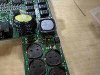
Holy crap I found a leaker!
1E8FA1C6-631C-46DB-906B-D61DCE493BD6.jpeg
The 33uf 25v cap here spilled its guts alright. Doesn’t smell like fish which is odd but that’s cap leakage if I’ve seen it. Time to recap your 1400s folks!
 

3lectr1cPPC

Well-known member
Probably….
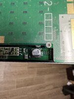
Gonna have to do this one later. Smallest clearance I’ve ever done perhaps. Got a real tiny tantalum to replace it, should be able to manage. This one’s Unit 3’s LCD though, Unit 1’s LCD is the one I’m recapping for now. Unit 1 isn’t apart yet. Probably should get the caps to do them all soon though :(
33B5D3B0-B848-431E-8562-B79A11DAB632.jpeg
 

3lectr1cPPC

Well-known member
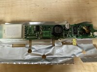
Inverter’s done. That just leaves the one awful LCD cap once Unit 1 comes apart.
96150F5A-663B-4935-A99E-9D9012DE947E.jpeg
I realized I was somehow missing a 10uf 50v cap when I went to my stash, so I had to get creative. Grabbed a spare 5300 inverter board from my parts bin. I had started to recap it months ago but I realized my 2.2nd 50v replacement was way to big so I only replaced the 10uf. Now it’s missing both! It’s just a spare, will recap it if I need it in the future. Next I think I’ll get unit 2 apart in order to install the first of my two 3D printed hinge fix parts. Going to practice on the less important of the two first, I want to get the fitment perfect for the main.
 

3lectr1cPPC

Well-known member
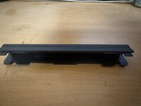
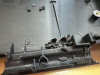
Disassembling Unit 2 now. Well, just the top half. And well, someone’s been in here! Center clutch clips came pre-snapped.
E3061E6F-56DB-437F-A304-3E3DB5E10911.jpeg


Edit:
The first blood of this project has been drawn.

PowerBook 1400 Rear LCD Housing Metal Foil - 1
3lectr1c - 0
 
Last edited:

3lectr1cPPC

Well-known member
Even though this is my 4th time installing one of these hinge fix parts - this part never stops hurting a little inside.
70C24689-D80F-49F8-BD1C-87C7398812D0.jpeg
 

3lectr1cPPC

Well-known member
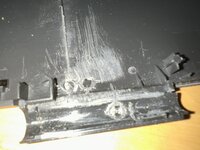
This may look like the standoffs are almost all gone, I sadly expect from experience that I’m probably at most 50% done with this side. There’s a lot of time with these just trying to get it fully perfectly gone, which takes a lot of time and sanding.
0CD7E61A-D24C-432F-91BB-884829BD2271.jpeg
 

LaPorta

Well-known member
Probably….
Gonna have to do this one later. Smallest clearance I’ve ever done perhaps. Got a real tiny tantalum to replace it, should be able to manage. This one’s Unit 3’s LCD though, Unit 1’s LCD is the one I’m recapping for now. Unit 1 isn’t apart yet. Probably should get the caps to do them all soon though :(

Don't do those as-is. My guide page here starts off detailing how to get at those caps without jeopardizing the screen.


I am curious: what is this hinge-fix mechanism you have?
 

3lectr1cPPC

Well-known member
Will look into doing that - thanks. I think I could get it done as is but better to not risk it I suppose.

Hinge fix mech is the same shim that we've talked about in different threads before done by AEChadwick. Going to JB Weld it on good and hope it stops the cracking. Unfortunately I've just realized that both my prints may be slightly out of proportion. I'll have to see once the sanding is done, but only one side fits the structuring at a time. May have to chop it in half and remove a slight bit of material. Shouldn't be too big a deal either way.

Also of the two LCDs I've seen so far, one had two caps like your photos showed, while the other one only had the larger of the two. Both are the same general part number but the text under is different. The two-cap LCD I have is my dead one that's full of lines.
 

LaPorta

Well-known member
I too have seen both of those: they seem to be different revisions of the same Sharp part number.
 

3lectr1cPPC

Well-known member
I guess we'll see what the screen I'm going to actually recap (still assembled in unit 1) has to offer in terms of caps.
 

3lectr1cPPC

Well-known member
Good to know. I'll look into it. Using what I've got on hand at the moment.
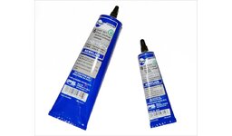
In the past I've used a mix of Plastruct Plastic Weld and traditional superglue, which has worked excellently on my PowerBook 145 and my 170, but completely failed on my 150. If you don't get the application just right, right away, it fails to hold long-term. JB Weld is the only stuff so far that I've tried that hasn't been a nightmare to work with, and has been strong enough to hold well under stress. It's very rigid once hardened, which I'm hoping will help add extra rigidity to prevent cracks.

Will definitely look at your stuff though. I'm always up to find more options here for this sort of stuff. Plastic's a tough thing to adhere and every product seems to have its disadvantages, JB weld included.
 

3lectr1cPPC

Well-known member
Despite how it looks I’ll bet I’ve got a solid hour of careful sanding left here. Definitely my least favorite part of laptop repair this, but hey, if it works it works.
EFAF4E12-B146-4819-9C47-3CD3E3E31120.jpeg
At this point I can test fit it and it’s good. Won’t need to cut anything, although I’m going to have to get creative to clamp it down as I don’t own any proper clamps. Will have to put some heavy but not too heavy things on it as it’s a tight fit. I’m very hopeful for a good result!
CA9144E2-0CAB-4603-873F-D889000BB5E1.jpeg
 
Last edited:

3lectr1cPPC

Well-known member
Thanks! Me neither. Fitment is being a real pain right now. Parts just aren't sitting flat, it's really the little teeny lips left from the structuring at the bottom of the supporting plastic that keeps it from doing so. That's the worst bit and what I'm dealing with not. I'm currently taking more structuring bits out and sanding flat. Can also sand the 3D print a bit as well if that's required. If that doesn't get it sitting completely flat, I'll cut it in half. I feel like it may be just a fraction of a millimeter too wide or something. It's a tough install for sure.
 

3lectr1cPPC

Well-known member
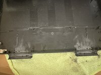
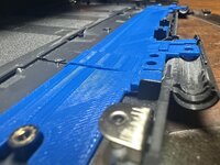
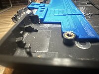
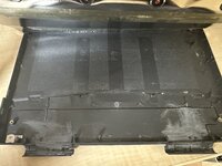
Final fitment test. It’s not absolutely perfect but I think it’s about as darn close as I’m going to get. Going to give a last sanding touch up to the left side then the JB Weld goes on.
34B91C11-A096-46A7-964F-FA53C0902EC4.jpeg
AB88B79D-EF31-4A17-9424-1F43555FDB78.jpeg
E50648FD-DB76-47D3-B709-FF9BB3360F4B.jpeg
 
Last edited:

3lectr1cPPC

Well-known member
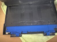
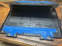
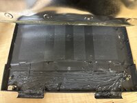
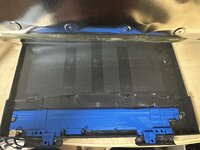
Alright. I’ve applied the JB weld and left the part to set! Here’s a few photos of the application process.

EF82E3D2-5D2C-48D1-92AC-17B06C91A037.jpeg
I always start by drawing a sharpie line around the part.
99D7C679-3964-4B9E-8185-BA9BEEF2120C.jpeg
JB Weld applied and mixed.
EB247796-7E7C-4DAD-AD56-D3915F02132D.jpeg
Part set.
CB1A7043-43B9-4BE1-8290-4FDDE51B174E.jpeg
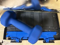
Weight added to the middle, which was the only spot at the end that the part was bowing up on at all. I’ll remove it next morning once the JB has set.

Now the fun part begins. We all get to sit here and wait 48 hours for it to fully cure because no chances are being taken here! Let the waiting commence.
 
Top