jmacz
Well-known member
Recently saw two PowerBook 5300 series laptops on eBay. One was a 5300c listed as parts only and apparently had some keyboard and chassis issues. The second was a 5300cs listed as parts only and apparently would not get past a sad mac with death chimes. I was only intending to pick up one but both of my offers were accepted and so I ended up with both. (That should teach me a lesson about assuming a low offer won't get accepted). I would like to think that this impulse buy was due to @3lectr1cPPC ...  but in reality as is always the case, I kinda wanted one. Not two though.
So I received a PowerBook 5300c and a PowerBook 5300cs a couple weeks ago.
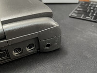
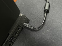
Both seemed to be in good shape physically but were both missing the rear port doors. They each had a non functional battery. One had a floppy, the other had a Zip drive. Neither would boot... one was actually missing a power port! The other did the sad mac with death chimes as the listing said. And on this sad mac one, after the first few boot attempts, the power port broke loose. Nice.
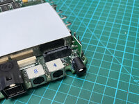
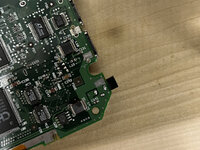
Time to take them apart. Here's a picture of the 5300cs's loose power port.
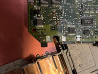
It looks like it fell off before and someone did a really poor job soldering it back on. I was concerned on initial glance based on the black areas that this laptop had a power surge or something. But on closer inspection, it was just dirty. For the 5300c (the one with the missing power port), I found it inside the case (phew!) rattling around.
The battery bay didn't really have any corrosion which is great. The mother board capacitor had not leaked on both units. All the parts seemed to be present although it was very clear both units had been disassembled by someone and not put together properly. And the 5300c was missing lots of screws.
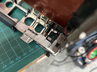
Onto the lids, both suffered from broken standoffs. Broken lid latch spring pins. Broken speaker mounts.
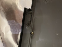
@3lectr1cPPC tells me this speaker mount is always broken, one side or the other.
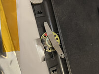
I thought it was funny that the lid latch wasn't springing back when you slide it... here's why:
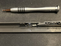
More broken standoffs.
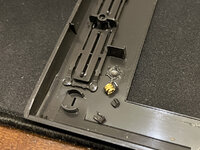
and more...
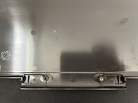
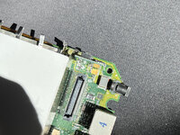
Ok, first thing was to fix the power ports. Cleaned up both the board and the port itself, then remounted, soldered them back on, and then used some epoxy to ensure it had more strength and the solder joints were not taking all the stress.
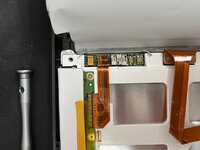
Next was the caps. I replaced the stock caps on the display (5300cs), the inverter boards (5300cs and 5300c), the motherboard (5300cs and 5300c), and the power unit (5300cs and 5300c). Here's the display from the 5300cs (this is the Sharp version):
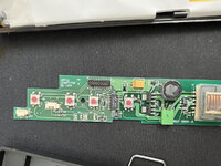
And the inverter boards:
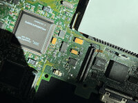
And the motherboards:
And finally the power units:
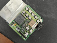
Ok, one note there. The caps above are Nichicons. When I got them I was annoyed as I thought Mouser had sent me incorrect 100 volt capacitors when I had ordered 100uF 35V capacitors. I decided to measure one with my multimeter and it read 100uF. Ok that's good, so what's up with the 100V, did they send me 100V rated capacitors instead of the 35V I requested? I looked up the data sheet for the Nichicons. Turned out they are the correct ones. Nichicon uses codes for their voltage ratings. So the second row is actually "100 V"... the 100 is for 100uF and the V according to their data sheet represents 35Vs. Go figure.
Next up was the damaged stand offs.
I took measurements of both parts of the display housing and modeled some replacement 3D printable standoffs:
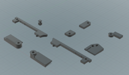
There isn't much room inside housing so I had to make the replacements small. I was concerned at first that there would not be enough surface area for a good bond with the plastic. I didn't think super glue was going to work but figured epoxy would work.
The little square R2D2 sensor like thing in the upper left.. what is that? Well, my lid latch spring pin was broken. Needed to replace it.
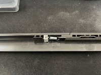
The above picture is with the piece epoxied to the lid and the spring mounted. Latch works again! I 3D resin printed this piece. Why is it clear? Well, I had printed some light pipes recently and was too lazy to clean out the resin tray so printed it with clear resin.
Here are the rest of the pieces printed in ABS:
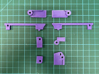
The top two pieces are for the outer lid. The next two pieces are for the inner lid (with the hole for the LCD). They fit next to the speaker (and include a new mount point for the speaker bracket). The final four pieces are replacement standoffs for the inner lid.
Not all of these standoffs broke on my lid so I didn't get to test most of them. But I did line them up and it looked like they would fit just fine. I will make the models available in this thread for others to use. Note that you will need to cut off some of the original plastic and sand down any stubs first. I would use epoxy. I don't think super glue will cut it.
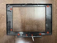
The red regions above need to be free of plastic so that the new 3D printed pieces can fit. Now some pictures of the new replacement standoffs:
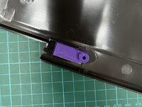
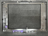
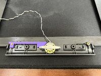
Yay, speaker mounted properly.
And now with the hinges mounted again:
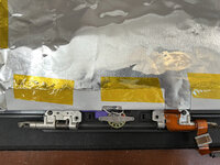
Both laptops are now back together and the new standoffs are working as expected. Lid feels good but I'm still handling them gingerly out of habit. Both laptops are booting now and seem to work fine. Both had 750MB hard drives that work as well as 32MB of memory. I tested the floppy drive and it works. I have yet to test the Zip drive.
I am now in the process of putting a ZuluSCSI in one of them. The issue is that it won't mount the way the hard drive did as the Zulu is lacking a side mounting mechanism.
EDIT: nevermind, should have realized these PowerBooks use IDE. Thanks @3lectr1cPPC !
So I received a PowerBook 5300c and a PowerBook 5300cs a couple weeks ago.
Both seemed to be in good shape physically but were both missing the rear port doors. They each had a non functional battery. One had a floppy, the other had a Zip drive. Neither would boot... one was actually missing a power port! The other did the sad mac with death chimes as the listing said. And on this sad mac one, after the first few boot attempts, the power port broke loose. Nice.
Time to take them apart. Here's a picture of the 5300cs's loose power port.

It looks like it fell off before and someone did a really poor job soldering it back on. I was concerned on initial glance based on the black areas that this laptop had a power surge or something. But on closer inspection, it was just dirty. For the 5300c (the one with the missing power port), I found it inside the case (phew!) rattling around.
The battery bay didn't really have any corrosion which is great. The mother board capacitor had not leaked on both units. All the parts seemed to be present although it was very clear both units had been disassembled by someone and not put together properly. And the 5300c was missing lots of screws.
Onto the lids, both suffered from broken standoffs. Broken lid latch spring pins. Broken speaker mounts.

@3lectr1cPPC tells me this speaker mount is always broken, one side or the other.

I thought it was funny that the lid latch wasn't springing back when you slide it... here's why:

More broken standoffs.

and more...

Ok, first thing was to fix the power ports. Cleaned up both the board and the port itself, then remounted, soldered them back on, and then used some epoxy to ensure it had more strength and the solder joints were not taking all the stress.


Next was the caps. I replaced the stock caps on the display (5300cs), the inverter boards (5300cs and 5300c), the motherboard (5300cs and 5300c), and the power unit (5300cs and 5300c). Here's the display from the 5300cs (this is the Sharp version):

And the inverter boards:

And the motherboards:

And finally the power units:

Ok, one note there. The caps above are Nichicons. When I got them I was annoyed as I thought Mouser had sent me incorrect 100 volt capacitors when I had ordered 100uF 35V capacitors. I decided to measure one with my multimeter and it read 100uF. Ok that's good, so what's up with the 100V, did they send me 100V rated capacitors instead of the 35V I requested? I looked up the data sheet for the Nichicons. Turned out they are the correct ones. Nichicon uses codes for their voltage ratings. So the second row is actually "100 V"... the 100 is for 100uF and the V according to their data sheet represents 35Vs. Go figure.
Next up was the damaged stand offs.
I took measurements of both parts of the display housing and modeled some replacement 3D printable standoffs:

There isn't much room inside housing so I had to make the replacements small. I was concerned at first that there would not be enough surface area for a good bond with the plastic. I didn't think super glue was going to work but figured epoxy would work.
The little square R2D2 sensor like thing in the upper left.. what is that? Well, my lid latch spring pin was broken. Needed to replace it.

The above picture is with the piece epoxied to the lid and the spring mounted. Latch works again! I 3D resin printed this piece. Why is it clear? Well, I had printed some light pipes recently and was too lazy to clean out the resin tray so printed it with clear resin.
Here are the rest of the pieces printed in ABS:

The top two pieces are for the outer lid. The next two pieces are for the inner lid (with the hole for the LCD). They fit next to the speaker (and include a new mount point for the speaker bracket). The final four pieces are replacement standoffs for the inner lid.
Not all of these standoffs broke on my lid so I didn't get to test most of them. But I did line them up and it looked like they would fit just fine. I will make the models available in this thread for others to use. Note that you will need to cut off some of the original plastic and sand down any stubs first. I would use epoxy. I don't think super glue will cut it.

The red regions above need to be free of plastic so that the new 3D printed pieces can fit. Now some pictures of the new replacement standoffs:


Yay, speaker mounted properly.
And now with the hinges mounted again:

Both laptops are now back together and the new standoffs are working as expected. Lid feels good but I'm still handling them gingerly out of habit. Both laptops are booting now and seem to work fine. Both had 750MB hard drives that work as well as 32MB of memory. I tested the floppy drive and it works. I have yet to test the Zip drive.
EDIT: nevermind, should have realized these PowerBooks use IDE. Thanks @3lectr1cPPC !
Last edited:

