• Updated 2023-07-12: Hello, Guest! Welcome back, and be sure to check out this follow-up post about our outage a week or so ago.

PowerBook 1400c/166 restoration/combination thread

3lectr1cPPC

Well-known member
It would go completely nuts if my hands weren't completely and utterly dry. It's so bad that even using the trackpad for a couple minutes, the microscopic amount of moisture created from just USING the trackpad would cause it to go nuts. Did a video demo of the issue:

In any case, do you know how to swap the touchpad modules between the plastic they're attached to? Didn't see an obvious way and I don't want to break anything.
 

joshc

Well-known member
Wow. Who knew getting into this hobby would require so much manual labour?

Hope this turns out well, it's looking good so far.
 

MacUp72

Well-known member
Oh no... I really should recap my 1400c shouldn't I. 😬

oh yes, I'll have to do this, too.. my 1400c works fine but I can tell from the muffled startup chime it needs a recap.. not enjoying this.

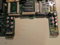
referring to this great tut by LaPorta I wonder if instead of the red, new electrolytic caps, tantalum ones can be used..like those yellow ones above it, I prefer those from the soldering standpoint.

IMG_5849.JPG
 

3lectr1cPPC

Well-known member
Definitely recap it, but I doubt the sound would go out on these like on some desktop macs when the caps go bad. These seem to be all strictly power related, basically like the DC board on the 5300.

I don’t think they make tantalum caps with those value’s unfortunately. At least, not practically available ones. Honestly the electrolytic caps are barely more difficult to install than a tantalum once you get used to them.
 

3lectr1cPPC

Well-known member
I do have some other updates to talk about today, even if the screen housing isn’t done yet.
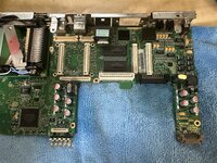
To start, I did finish recapping the logic board yesterday.
7E71A5F2-9395-4DCF-8BD4-3E717594C85D.jpeg
Yeah, the solder joints don’t look great. I did use flux, yes, but it’s just really tough. These PowerBook DC sections are just absolutely full of big ol’ ground planes and I have to use a thin soldering iron tip to be able to get into the tight spaces, just how it is, with my basic iron at least. Once the IPA that I used to wash the flux off, I’ll go ahead and give the recapped board a test.
 

3lectr1cPPC

Well-known member
Working!
35D0D6C4-3714-4C59-95A9-7548E3225BD5.jpeg
Oh, and I can also now confirm 100% that a 166MHz CPU card doesn’t work in a 117MHz board. Had heard that online but wanted to confirm. Doesn’t start.
 
Last edited:

LaPorta

Well-known member
That is documented in the Apple Repair Manual as well. Do you have a copy of it? It really helped with my take apart.
 

3lectr1cPPC

Well-known member
Service source to the rescue! Touchpad module is removed from the bad condition keyboard surround, thank you for the suggestion to check there.
D3939091-0CBC-42E1-A2E4-85BB4BBF3378.jpeg
 

3lectr1cPPC

Well-known member
Like everything in the project, it’s hard to keep track of which parts I’m swapping where…

Unit 2’s module is going in Unit 1’s surround.
Unit 3’s module and clicker are going in unit 2’s surround.
Unit 1’s clicker button is going with unit 1’s surround.
That leaves Unit 1’s module, Unit 2’s clicker, and unit 3’s surround.

The completed parts will basically be as follows:
Final main PowerBook gets the best clicker, and a working module.
Final secondary gets the hopefully working module and the pretty good clicker
Parts unit gets the faulty module and the worst clicker.

And yes, I can barely keep track of what I’m doing myself. I don’t expect you too! 😅
 

3lectr1cPPC

Well-known member
God getting these back together is a nightmare. Fitment here just won’t go together, can’t tell whats keeping it from working. Something with the god awful PCMCIA doors I’m sure but from what I can see it should just fit, no problem. But it doesn’t. Getting the trackpad cable in too, the absolute worst.
any ideas? I genuinely don’t know why it won’t fit. It’s not some hard piece that’s catching too, if I press really hard on it, it goes down almost all the way. But I shouldn’t have to do that and of course there’s no way to hold it that way.
5C103364-E903-401C-82FE-1591CC7FB550.jpeg
 

3lectr1cPPC

Well-known member
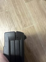
I think it's getting caught on the metal shield attached to the logic board, which is annoying. It's this peg on the top case and I'm not sure why it's necessary. If I can't get it to fit, I might just cut it off.
 

LaPorta

Well-known member
That's odd, I never did have that problem. Might be worth disassembling and reassembling in order in the manual to be sure.
 

3lectr1cPPC

Well-known member
The issue is that the metal shield slightly bent in when removing the logic board. There's no good way to bend it back that I can tell without pulling the LB again which risks the fragile PCMCIA doors again... they already broke a bit, not enough to affect functionality. Think that's what I'm going to do though :( :( :(
 

3lectr1cPPC

Well-known member
Bent it back and we're mostly good now. But I left out the PCMCIA eject board so apart again it goes haha....

Next I get to play the "where did I put the left side rear foot" game. My favorite!
 
Top