• Updated 2023-07-12: Hello, Guest! Welcome back, and be sure to check out this follow-up post about our outage a week or so ago.

SuperMac Spectrum 24/V Display Problems

jmacz

Well-known member
Another year, another SuperMac Spectrum 24 card to debug. :oops: Yes, I am 4/4 on obtaining cards with issues and batting 2 for 4 so far in fixing them. I fixed a dead 24/IV... fixed a slightly malfunctioning 24/PDQ... still continue to have some problems with a 24/III.

The latest is a SuperMac Spectrum 24 Series V. It came to me having suffered some damage:
  • Bent metal bracket (fixed).
  • Broken Nubus connector (fixed/replaced).
  • Broken ferrite bead (fixed/replaced).
  • Missing ferrite bead (fixed/replaced).
  • Missing 2 capacitors (fixed/replaced).
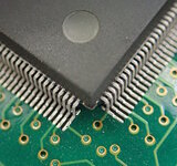
  • Bent pin on the SMT02S chip (fixed).
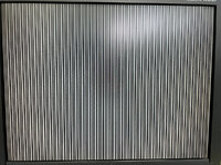
Symptoms/Problem: display has colored lines (vertical, horizontal, diagonal, patterned) all over the screen.

Test Setup:
  • Macintosh IIci with 16MB of memory (also tested on a Quadra 700 with same results)
  • External ZuluSCSI with System 7.1.1
  • SuperVideo Control Panel v3.1
  • SuperMac Spectrum 24 Series V card with ROM version 3.1
  • Resolution / Color Depth: 1024x768 @ 75Hz with 24bit color (same problem in other color modes)
Ruled Out:
  • Monitor - tried multiple monitors including LCDs, Trinitrons, all the same problem.
  • Computer - tried multiple computers including a IIci and Quadra 700.
  • ROM - tried the v3.1 ROM as well as the v3.0 ROM for the Spectrum 24 V.
More Info

With the fixes listed above completed, I have been testing the card as the secondary video. The primary is the onboard video on a IIci. The primary monitor is an Apple M1297 13" Trinitron and the secondary monitor is a NEC 52V LCD 15" monitor. (Note that the issue happens regardless of whether the SuperMac card is used as primary or secondary).

As the IIci is booting, I see one of two things:
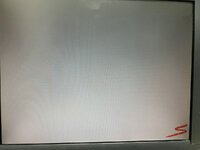
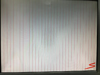
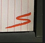
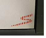
IMG_7039.JPG IMG_7040.JPG

More often than not, the second one (right picture). The left picture has SuperMac logo with some missing vertical lines in the SuperMac logo. The right picture has lots of red vertical lines (including in the SuperMac logo) that should not be there.

I figured base on the above, something's wrong with one of the traces as the issue is very regular in spacing. I figured it's with the handling of red.

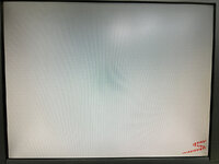
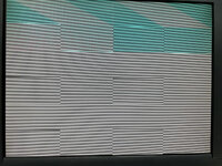
But as soon as the Finder loads, the monitor shows this (or something similar - it's random and not always the same):
IMG_7041.JPG

First there are rows of lines across the entire screen (that's not the monitor). Two rows of gray and two rows of black repeating across the entire screen. Then there are these strange rectangles again evenly spaced. And then there's a blue color diagonal shape. So it's not just an issue with red. Something else is going on.

Now I tend to use the Desk Picture control panel to set a background picture on System 7.1.1. This is 3rd party piece of software. I can choose a different picture for each monitor. And for what I showed above, I have not installed the Desk Picture control panel yet so this is occurring without this control panel installed. Now I install the Desk Picture control panel and reboot. Same issue during boot and similar crazy colored patterns as the above once the Finder loads.

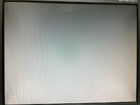
Now I open the Desk Picture control panel, select the SuperMac Spectrum 24 V / NEC LCD monitor so that I can choose a desktop background picture. As I do this, the NEC LCD erases the screen (this is what normally happens) and I see this:
IMG_7043.JPG

Ignore the waves, that's my iPhone / LCD and refresh rates. The picture was clear, no artifacts, solid gray as it should be! I then choose a picture (which is obviously too small) and the picture pops up on the screen (this is still in the preview mode of Desk Picture):

IMG_7044.JPG

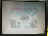
As you can see, it's clear and picture is perfect. No lines, no issues. I then hit Save and the preview goes away which then causes this on the screen:
IMG_7045.JPG

It looks like it failed to erase some vertical lines and there's some weird colored boxes visible in the upper half of the screen. And then a second later I see this:
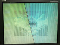
IMG_7046.JPG

Strange pattern. At this point it's back on the Finder but Desk Picture has not drawn the background yet. And then a few seconds later, Desk Picture updates and draws the picture I selected:
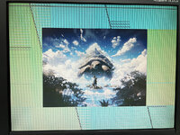
IMG_7047.jpg

The picture itself is perfect. But the screen still has that weird garbage in the background.

This is all completely reproducible. Every time. The patterns change and are different. But I continue getting a messed up logo screen with red lines. And then garbage on the screen when the Finder loads. And then a perfect picture after Desk Picture draws the chosen image.

With Desk Picture completely removed from the System Folder, everything is the same except of course there's no picture of the turtle. So this issue is not caused by Desk Picture.

TroubleShooting

I've checked continuity for all 24 memory chips on the SuperMac Spectrum 24 V card. I ended up mapping where every memory pin goes and continuity is good. I used hotair to reflow the pins on the SQD-01, SMT02S, three BSR03, and ADV473 chips. I mapped out the data lines coming from the Nubus connector and those all seem to have proper continuity.

It's weird because if the red vertical lines were permanent, I would say it's a trace somewhere. But those red lines appear/don't appear only on boot. After I reach the Finder, the garbage is on the screen and the issue doesn't seem to be consistent as the picture obviously renders perfectly over them.

I feel like some erase operation is not working right. When it renders/draws, it's ok. But when it tries to erase, it fails? At least it looked that way but not everything is neatly explained by that.

Need Help

Before I go find and buy a memory chip so that I can begin swapping them out one by one, need help on other suggestions or things to check. I wouldn't think it's the memory chips given I'm getting successful pictures drawn over the garbage and the issues aren't isolated to a particular region of the screen.

Anyone have any ideas on what could cause the behavior I'm seeing above?

I'm hoping it's fixable, and it's not one of the proprietary SuperMac chips that's faulty (although it seems like it will be).

Paging the SuperMac professional @MacOSMonkey for help :)
 
Last edited:

jmacz

Well-known member
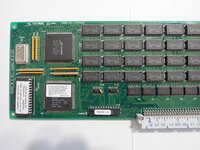
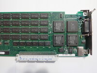
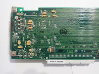
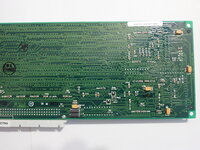
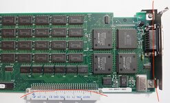
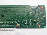
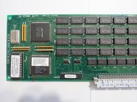
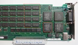
Anyone with a Spectrum/24 Series V, if you could upload a high resolution picture of both the top and the bottom of your board, that would be helpful to me. Thanks in advance!
 

Melkhior

Well-known member
Is that an accelerated card? Is acceleration enabled? Try without if so.

To me, the fact that the pictures are drawn fine suggest the CPU/DRAM -> VRAM path is fine, including the VRAM themselves. Same for the VRAM -> DAC -> video output path. But it seems than whenever the Mac does something that could be accelerated (rectangle fill, blitting, things like that), something wacky happen to your screen. That suggests that the acceleration part is the issue. The first screen erase (with the supermac logo) is probably part of the primary/secondary/open call, and might always be impemented by an acceleration engine so that would likely stay buggy.

If it's not acceelerated (or really disabled), then I'm at a loss. It could be a read vs. write thing (where writes work OK for the picture, but readback from VRAM are messed up) but the patterns don't really match that. The screen is messed up in a way the suggests more addressing issues, but from NuBus address lines have no reason to work for writes and not reads.
 

MacOSMonkey

Well-known member
At primary INIT, the board you have is in 1-bit mode and the CLUT is being programmed for red (0) and gray (1) to display the SuperMac splash screen. Earlier SuperMac boards programmed the CLUT to black/white and used a half-tone gray screen and black banner (various Spectrum boards - Spectrum/8 (SpecB), Spectrum/8 Series II (SpecC), Spectrum/8 Series III, etc.).

Anyway, the board should be displaying mostly gray pixels, indicated by a 1 bit, but, instead, is showing red/0. Also, this issue is serially repeating across the screen (interleaved memory organization). So, since something is always reading 0 when it should be reading 1 and is a repeating issue, it potentially points to bad VRAM or a memory access, or maybe something being shorted to ground, etc.

Also, since the problem is present at Primary INIT, it has nothing to do with the accelerator code or the SQD01 hardware. The accelerator code/functionality is not loaded until Secondary INIT (right before the desktop comes up). Anyway, the patterns your images show point to bad VRAM or block of bad data (or I guess it could also be a bad address line).

If you were manipulating pins on the SMT01, make sure that there are no solder or other pin shorts/damage.
 

jmacz

Well-known member
Is that an accelerated card? Is acceleration enabled? Try without if so.

Yup, it's accelerated and disabling acceleration doesn't seem to help.

Let me know if you need any particular close-ups or measurements.

Thanks David! I have a 24/IV board and it's very similar to my 24/V. I just wanted to confirm a few things near the nubus connector and these pictures helped, thank you!

Also, since the problem is present at Primary INIT, it has nothing to do with the accelerator code or the SQD01 hardware. The accelerator code/functionality is not loaded until Secondary INIT (right before the desktop comes up). Anyway, the patterns your images show point to bad VRAM or block of bad data (or I guess it could also be a bad address line).

Yeah, I was hoping it wasn't the SQD01, SMT02S, or BSR03 chips as I would need to find a new donor board in that case which then basically means this board is useless. I'm hopeful it's something else.

The initial gray screen with SuperMac logo is actually the "cleanest" .. just those red lines which seemed to suggest a VRAM issue. But as it starts loading the other INITs, the screen gets worse, lots of patterned boxes (pictured earlier), and then when it gets to the desktop, it's the worst, lots of colors and still patterned but all over the screen.

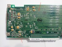
I'm using @David Cook's picture to mark where the damage was when I received the board (since my board is semi disassembled right now)..

P2175320.JPG

The nubus connector was cracked and one chunk of the plastic on one side was entirely missing. The metal slot bracket was bent out of shape. Basically looked like something hit it while it was installed causing the bracket to deform and nubus connector break. (I took the metal bracket off, bent it back into shape and reinstalled it. I also replaced the nubus connector with a brand new molex one).

P2175322.JPG

There was a broken trace where the top arrow is. And the board was cracked where the bottom red line is visibly severing one trace in that area (I've repaired both).

P2175325.JPG

L3 was missing the ferrite part (just the metal core was still there and had continuity). L1's ferrite was cracked but still there but moving around. The two caps on the right side were missing. The remaining solder did not suggest they broke off, looks like the previous owner desoldered them.

P2175318.JPG

One of the SMT02S pins near the arrow was bent and touching the next pin.

So basically the nubus connector side of this board suffered some damage so I've been concentrating in that area but I can't find anything wrong... I completely desoldered the old nubus connector and checked the board before installing the new one so I don't think it's there. I have been looking around the U9, U1 through U4, and U50 chips, as well as U43 and U42 as they are in the vicinity of the damage. U1 through U4 in particular seem to be TI AS640 which when searching might be bus transceivers so wondering if any of them might be damaged? I reflowed the joints but didn't help.

I'm right now in the process of removing the VRAM chips one by one and focusing on the primary init logo screen. After toning out all the memory chips, I believe it's these that are responsible for red as they have connectivity to the BSR03 chip associated with the red inputs going to the RAMDAC.

P2175320.JPG
 

Melkhior

Well-known member
Anyway, the patterns your images show point to bad VRAM or block of bad data (or I guess it could also be a bad address line).
Wouldn't "reliably bad" VRAM (as the boot screen would imply) not allow the display of a clear picture, ever? That's what puzzles me. At some point, the DAC reads good value from the VRAM and push them to the screen with no issue, and something has written the data in the VRAM reliably as well.

During Primary INIT, do all access to the VRAM comes from the CPU, and therefore over the NuBus? Or could something else on the board be driving the signals to the VRAM (data and/or addresses)? If there's two different set of drivers on the bus(es), then one could be fine and one dodgy - with the NuBus one being fine presumably as the data for the picture comes over NuBus.

If there's just the one path to write to the VRAM, I don't see how they could alternate between "reliably not working" (boot screen, desktop) and "reliably working" (the background picture).

Hopefully @jmacz will figure out what's going on and resolve the issue, I'm interested in what caused that behavior.
 

MacOSMonkey

Well-known member
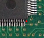
Sorry - my post above should have said SMT02 (not SMT01). Anyway - it looks like there might be something happening in the lower right corner of the SMT02 in your picture -- is there a bent pin/short there? See the red dot. Maybe what I am seeing is just an optical illusion, but it looks like a pin has been pushed inward and is angled off its pad.

smto02question.png

In response to my comments about bad VRAM, I'll read the original post again and think about it. I responded after seeing the boot screen.

Whenever the ROM is executing (68K code), it is running on the Mac CPU. So, any writes to VRAM are going over Nubus (such as during Primary INIT). Accelerated writes are on-board translations that do not go over Nubus, except for maybe some setup. If there is a problem with VRAM or maybe addressing, the pattern will vary in a regular way based on bit depth. In the 1-bit boot screen image, it looks like the problem is occuring every 32 pixels -- or bit 6 (0x20) of the data for each byte write...but you can verify that by putting the board in 1-bit mode at the desktop and verifying that the striping does not vary. At the desktop with normal white/black CLUT programming for 1-bit mode, you should see black striping every 32 pixels (or whatever it happens to be).

Also, if you are seeing artifacts in modes other than 8-bit and 24-bit, then that is another clue that it is not acceleration-related.

I guess if the Nubus connector area of the board took an impact, then there could be a problem with one of the data lines perhaps -- broken trace? Your replacement job looks good.
 
Last edited:

jmacz

Well-known member
Sorry - my post above should have said SMT02 (not SMT01). Anyway - it looks like there might be something happening in the lower right corner of the SMT02 in your picture -- is there a bent pin/short there? See the red dot. Maybe what I am seeing is just an optical illusion, but it looks like a pin has been pushed inward and is angled off its pad.

smto02question.png

That picture is from @David Cook's board. That's not mine. I reused his pictures in this thread as my board's in the garage in pieces right now :) So David probably should check that on his board but all the pins are good on my board experiencing the issue.

but you can verify that by putting the board in 1-bit mode at the desktop and verifying that the striping does not vary. At the desktop with normal white/black CLUT programming for 1-bit mode, you should see black striping every 32 pixels (or whatever it happens to be).

I will cycle through the modes again and see if I can see this spacing.

Whenever the ROM is executing (68K code), it is running on the Mac CPU. So, any writes to VRAM are going over Nubus (such as during Primary INIT). Accelerated writes are on-board translations that do not go over Nubus, except for maybe some setup.

I agree with @Melkhior that given I can render a clean image on the deskop free of issues (at least via that Desk Picture wallpaper), that the nubus connection is probably ok?

For the boot screen with the SuperMac logo, that is coming from ROM and so the fact that it already has red striping issues means that particular problem isn't a nubus related one.

I think there's possibly multiple issues...

1.) The red stripes on the logo primary init screen suggests a VRAM problem (given the spacing, etc). Possibly with the VRAM modules related to red? My toning out of the VRAM chips suggests the VRAM is grouped by color... 8 for red, 8 for green, 8 for blue. Each group of 8 has connections that go to a single one of the BSR03 chips, and each of those BSR03 chips has connections going only to the red, green, or blue pins on the ADV473 RAMDAC.

2.) Although the image data itself seems to get to the card ok (given the ability to render an image properly in some cases), it seems like the actual output is getting corrupted. And it's weird that if there was a VRAM issue, why I'm not getting red stripes on the rendered image. That's weird too.

@MacOSMonkey what are the specific chips roles in the video output? It sounds like the SQD01 chip is handling acceleration. The ADV473 is the RAMDAC handling the analog conversion of red, green, blue. The BSR03 chips seem to be one per color (R, G, or B) but what is it responsible for in the pipeline? And what about the SMT02S chip? Trying to rule out chips to reduce where I'm looking for issues.

Seems more likely that the issue is due to the path towards the BSR03 chips perhaps? Less likely that it's related to the Nubus connection.
 

MacOSMonkey

Well-known member
I am traveling at the moment, so responding quickly -- a few more things...

- The ROM stores 68K code that is loaded/executed by the Mac CPU in the slot address space. So, when there is a write to board memory - like drawing to the screen during Primary INIT, it is going over Nubus. It's just writing bytes to board memory that are then translated to color output by the DAC.

- The fact that you see red at boot is because of how the CLUT is programmed - it is not related to a specific bank of RAM. The CLUT could also be black or green, etc. In 1-bit mode, there is no comparison with the RGB components of a 24-bit pixel.

- The frame buffer in RAM is always continuous from the origin/board baseAddr. In 1-bit mode, each byte write is 8 pixels of data. So, writing 0x00 draws 8 black pixels (or red, in the case of the custom CLUT for the boot screen) or writing 0xff draws 8 white ones (or gray in this case). In 8-bit mode, each byte write is 1 pixel of data (color or grayscale, depending on mode) -- in the Mac's 256 color/gray palette. In 24-bit ("true color") mode, each byte is one of the color components (RGB as 0xAARRGGBB) -- generally longword writes where the upper 8 bits (alpha channel) are ignored (unless specifically supported -- but not on these boards as far as I recall). Anyway -- each pixel is a long in 24-bit mode and there are "millions" of colors that are either converted through 3 single-channel DACs or a triple-channel DAC on later SuperMac boards.

- If there is an issue with bad data in a 24-bit value, you might not be able to easily detect it, depending on its significance. For example, if it's the LSB of one of the color components, everything may appear to be normal. 0x00fffeff vs. 0x00ffffff? - minimal difference. If there is a data line problem, it will be most apparent in lower bit depths, where bad data will have more visible (and periodic) impact on the analog output.

SMT (01, 02) is the graphics controller - SMT02 is an iterative improvement over SMT01
BSR (02, 03) are Bit-Shift Registers - BSR03 is an iterative improvement over BSR02
SQD is the graphics accelerator (or "Squid" chip). I think there was only ever 1 version - the SQD01 -- a great tape-out

Be sure to check the Nubus address/data lines, since Nubus had an impact and you had to replace the connector. Hope this is helpful.
 

jmacz

Well-known member
- The ROM stores 68K code that is loaded/executed by the Mac CPU in the slot address space. So, when there is a write to board memory - like drawing to the screen during Primary INIT, it is going over Nubus. It's just writing bytes to board memory that are then translated to color output by the DAC.

Ok, thanks. I had the wrong mental model that the image with logo was being read from within the board. But sounds like it's actually code that is executed (by the CPU). Got it.

Be sure to check the Nubus address/data lines, since Nubus had an impact and you had to replace the connector. Hope this is helpful.

I had checked all of the address/data lines for continuity with U1 through U4 (the four TI AS640 chips closest to the Nubus connector). Each one has near zero resistance and are giving a solid tone. Will keep looking.
 

jmacz

Well-known member
Not much progress.

I have the issue with or without acceleration enabled. I have the issue at all bit depths although at 1bit (black and white), I don't get all those weird patterns and colors. The issue at 1bit is limited to evenly spaced lines on the screen.

I have four of the VRAM chips off the board right now. The removal of three of those chips added additional red/gray lines to the boot screen (as expected) but none of them impacted the original lines. But one of them made no difference and it's not clear whether that tells me something or it's inconsequential as it's not clear to me how the frame buffer for the boot screen is spread across the VRAM chips.
 

jmacz

Well-known member
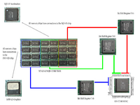
I'm trying to understand how the memory is laid out. From a connectivity perspective, this is what I'm seeing:

Memory Layout.png
The ADV 473 RAMDAC has 8 input lines for each of red, green, blue. I have highlighted those pins in the diagram above (R0-R7, G0-G7, B0-B7). I'm guessing each is a bit is part of the representation of an 8-bit color value?

Each of the BSR03 bit shift registers has connections to only one set of those pins (either for red, for green, or for blue). I have noted which BSR is handling each color. So U44 for R0-R7, and U45 for G0-G7, and U46 for B0-B7.

Looking at the VRAM chips, all of the VRAM chips as expected have shared and individual connections going to the SQD-01 and SMT-02S chips.

The VRAM chips seem to be grouped into 3 sets. The left set of 8 chips has both common and individual connections going to the U46 BSR03 (talking to the blue pins on ADV473). This left set of 8 chips have no connections to the other two BSR03s. The center set of 8 chips has both common and individual connections going to the U45 BSR03 (talking to the green pins on ADV473). And the right set of 8 chips has both common and individual connections going to the U44 BSR03 (talking to the red pins on ADV473). This seems to suggest the chips are grouped by color? Is that right?

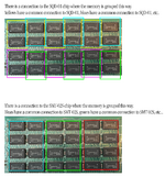
There's also some other groupings that can be seen by tracing the connections:

Memory Layout 2.png

There is a single common connection between some of the VRAM chips to the SQD-01 chip which follows the grouping above (top diagram). This is a grouping of 4 groups (group yellow, group blue, group violet, group green).

There is a single common connection between some of the VRAM chips to the SMT-02S chip which follows the grouping above (bottom diagram). This is a grouping of 3 groups and matches what I mentioned earlier about which chips talk to which BSR03 chip.

Boot Screen SuperMac Logo

What @MacOSMonkey mentioned earlier is that the boot logo screen is brought up during the Primary Init phase and it's 1 bit with a CLUT that contains only two colors, red and gray. A high bit is gray. A low bit is red. He also mentioned that they are grouped in bytes so a single byte in the frame buffer represents 8 pixels with each bit representing a single pixel (again, high = gray, low = red).

The Primary Init phase doesn't utilize acceleration. The ROM is responsible for rendering this boot logo screen. Based on my very limited knowledge, my current mental model of the flow is:
  1. Power on
  2. Bunch of Mac initializations
  3. Primary Init
  4. ROM code loaded and executed in the CPU (IO via Nubus)
  5. ROM code programs CLUT to contain 2 colors (red/gray) <- where is the CLUT stored? Is it within the BSR03s?
  6. ROM code executes instructions to render the logo screen (IO via Nubus back to the card)
  7. SMT-02S chip writes into the frame buffer / vram? (connection between SMT-02S and VRAM chips)
  8. Based on the diagrams above, it seems like the VRAM is grouped by color?? so does this mean that the number of pixels in the framebuffer is covered by 8 chips but each group of 8 chips handles one of the three RGB hues (at least in 24bit)?
    1. If the CLUT lookup is done within the BSR03s, then I would think that for the boot logo screen, you have 3 sets of the same data in the VRAM? Then each BSR03 does a lookup in the CLUT and outputs one of the R, G, B values to the RAMDAC?
    2. If the CLUT lookup is done before the BSR03s, then I would think that for the boot logo screen, each group of 8 VRAM chips holds only the data for its RGB component, so:
      1. All blue VRAM chips have either a 0x7f for the gray pixels or 0x00 for the red pixels
      2. All green VRAM chips have either a 0x7f for the gray pixels or 0x00 for the red pixels
      3. All red VRAM chips have either a 0x7f for the gray pixels or 0xff for the red pixels
  9. The three BSR03 chips set the appropriate R0-R7, G0-G7, B0-B7 pins on the RAMDAC for output
Let me know if I'm totally thinking about this incorrectly. Brain is fried from looking at pins all day. :)

Boot Screen: I'm only seeing uniform grays or pure red. No other colors or shades are present. It's all uniform.
1 Bit B&W Finder Desktop: I'm only seeing a uniform white or black, no other shades/brightness/etc. It's all inform.

If the above memory layout is correct (again, I am probably misunderstanding something), I would think that if a single VRAM chip was bad or faulty, then I would see different shades, not always a uniform color? For example, if one of the chips in the red grouping was bad, I would think that for the boot logo screen, I would see:
  • For a gray color:
    • Blue BSR outputs 0x7f
    • Green BSR outputs 0x7f
    • Red BSR outputs 0x00 or 0xff or some random value
    • Result: a non-gray red-tinted color for pixels that were held in the faulty VRAM chip
  • For a red color:
    • Blue BSR outputs 0x00
    • Green BSR outputs 0x00
    • Red BSR outputs 0x00 or 0xff or some random value
    • Result: black, or red, or some red-tinted color for pixels that were held in the faulty VRAM chip
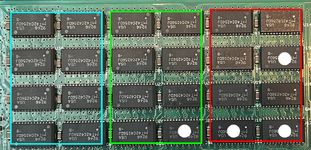
But after removing the four of the VRAM chips, I'm seeing missing reds which show up as grays. I removed the following 4 chips.

Memory Layout 3.png

The fact that I'm seeing grays and not some other tinted color seems to suggest that my understanding above is actually wrong. I must be too fried to see what I'm missing.

Here's the boot logo screen with these four chips missing.

IMG_7102.JPG

The missing parts of the logo are the same color (gray) as the rest of the screen. And here's the Finder desktop in 1bit black and white:

IMG_7101.JPG

I must be missing something.
 
Last edited:

David Cook

Well-known member
More often than not, the second one (right picture).

1. You said it was intermittent (the first part of your very first message) and that the board had significant physical damage. That sure suggests a cracked solder joint or hairline trace crack.

2. The solid lines are gone now. That suggests that one of the chips you removed is in the bad path. Put them back one at a time until the line reappears?

1708289183653.png 1708289368389.png
 

jmacz

Well-known member
1. You said it was intermittent (the first part of your very first message) and that the board had significant physical damage. That sure suggests a cracked solder joint or hairline trace crack.

Yeah, I agree. But I've reflowed basically every chip as well as the nubus connector without a change. My guess is if it's a trace crack, it might be in an internal layer which is why I'm hoping to better understand how the card works so that I can narrow down and see if I can find where and route around it.

2. The solid lines are gone now. That suggests that one of the chips you removed is in the bad path. Put them back one at a time until the line reappears?

1708289183653.png

The lines are also coming and going so not positive it's one of the chips I removed. But I'm thinking along the same lines and was gearing up to put them back on one at a time to see.
 

David Cook

Well-known member
The lines are also coming and going so not positive it's one of the chips I removed. But I'm thinking along the same lines and was gearing up to put them back on one at a time to see.

Can you show a picture with the solid line and the dark line on the logo? If the solid line appears where a blank line should be, then it is not a RAM issue. If a solid line appears elsewhere, then you haven't found the right ram chip yet. If the solid line appears at random locations each boot, then uhhh I don't know yet.
 

jmacz

Well-known member
Well... the lines just came back, without putting any of the VRAM chips back on the board. I had only plugged in the video cable to my LCD. So that does suggest a trace/joint issue somewhere.

I wiggled the card a bit and it's now stuck with the extra red lines on the screen. I did get one attempt with the red lines gone again but it's mostly stuck with the red lines now.

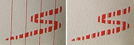
Here's a side by side of with and without zoomed in:

sidebyside.jpg

That looks like the entire vertical line is either red or gray.

I do feel like I have two problems right now though... one is to resolve this single line that keeps coming/going. The other is the array of shapes/colors when running above 1 bit color.

I'm going to place the four chips back on the board now watching along the way to see if a "correct" line reappears to rule out that chip. If I see one that doesn't change anything (and I'm certain I put the chip back on correctly) then that suggests the problem above is with one of the connections associated with that chip... although again, I'm curious about the frame buffer layout as I'm wondering whether any of these chips are inconsequential for this boot logo rendering.

On a side note: argh... need to be more careful. Lost one of the pads for one of the VRAM chips. Luckily it was a ground pad so I can easily use a bodge wire. But argh anyway. First pad loss in a very long time. 🤦‍♂️
 

David Cook

Well-known member
That looks like the entire vertical line is either red or gray.

This is really good news! You now know that the bad signal is not going through any of the chips that you removed. It is likely one of the other red chips.

>> The other is the array of shapes/colors when running above 1 bit color.

Maybe. Or, perhaps the RAM is being used for more than just a screen buffer. A bad memory chip could be affecting structures or operational data. Find and fix the bad line, and the card may just start working in the other modes.
 
Top