• Updated 2023-07-12: Hello, Guest! Welcome back, and be sure to check out this follow-up post about our outage a week or so ago.

SuperMac Spectrum 24/V Display Problems

jmacz

Well-known member
3 of the 4 chips are back on the board. The one remaining off the board is U25 which is part of the green group and seems inconsequential. Leaving it off for now.


Here are my notes from placing U15, U17, U18 back on the board:
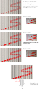

vertical line analysis.png

So I have 5 remaining chips to test to determine which one has that red vertical line in it. One of U14, U16, U19, U20, or U21. If I look at the datasheet for the VRAM module (which is a MT42C4256DJ-8 256K x 4 VRAM), here's the pinout:


VRAM Chip Pinout.png

From toning out all the memory chips (all pins), I've annotated above how they connect to the various components. I could not find where pin 20 QSF goes to on all the chips. It looks to be left disconnected.

The double greens are basically shared by most of the VRAM chips (all interconnected) and are connected to the SMT-02S. The double blues are basically shared by most of the VRAM chips (again, all interconnected) and are connected to the SQD-01. The double red for all the red group VRAM chips are shared and connect to the U44 BSR03 chip. The single blues are unique to each VRAM chip and connect to the SQD-01.

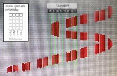
The single red (for the red group chips) are unique connections to the U44 BSR03 chip. Given that each "column" in the logo screenshot above is 4 pixels wide, I'm curious whether I can assume here that each pixel column is one of these pins? Or am I reaching?

If so, I need to identify the VRAM chip (of the remaining 5) and then one of these 4 SDQ1/SDQ2/SDQ3/SDQ4 connections to U44 BSR03.

I can probably do a resistance check on all of those pins before I remove any more of these VRAM chips.
 

MacOSMonkey

Well-known member
If you wiggled the card and the problem came back, then it could be a nubus data data line (which is card, not mac, since you tried multiple macs). Check the nubus lines and port carefully. It had an impact and could be damaged.
 

MacOSMonkey

Well-known member
The RAM addressing is interleaved for speed (IIRC), which is why you see the successive banding. Also, I will just say that you are a wildman! ^_^ It's awesome!
 

jmacz

Well-known member
I can probably do a resistance check on all of those pins before I remove any more of these VRAM chips.

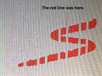
Resistance was low.. one pin on U20 was around 0.9 ohms versus all the other pins around 0.7 ohms but it's not the issue. I added a bodge wire and it didn't help.

If you wiggled the card and the problem came back, then it could be a nubus data data line (which is card, not mac, since you tried multiple macs). Check the nubus lines and port carefully. It had an impact and could be damaged.

Will have to take the port off again and check it. On my todo list.

The RAM addressing is interleaved for speed (IIRC), which is why you see the successive banding. Also, I will just say that you are a wildman! ^_^ It's awesome!

LOL.. I feel like I'm just throwing spaghetti on the wall right now.
 

MacOSMonkey

Well-known member
You don't have to remove the port. Just make sure there are no solder voids and test from the connector with pin jumper wires.
 

jmacz

Well-known member
You don't have to remove the port. Just make sure there are no solder voids and test from the connector with pin jumper wires.

Many of the data lines going to the Nubus connector are surface traces that run within the spaghetti of pins on that connector so the thought was to remove it so I can visually inspect the traces.

But made some progress. Will detail in my next post.
 

jmacz

Well-known member
Removed U20 and it wasn't the problematic one. Then removed U19, and bingo! Removing that chip caused the 4 pixel column I was looking for to go gray.

IMG_7118.JPG

So looks like the culprit is U19, at least for the boot logo screen issue. But this gave me an opportunity to learn a little more. I took the VRAM chip that was sitting at U19 and used it to restore U20 on the board. The problem did not follow the VRAM chip. That rules out the U19 VRAM chip as being the problem. It's probably good.

What does this mean? The possibilities are:
  • U19 had a partially broken solder joint thus resoldering a VRAM chip back into that slot might correct the problem.
  • One or more of the write pins going into U19 has an issue (either on the U19 side or on the src/dest side).
  • One or more of the read pins going out of U19 has an issue (either on the U19 side or on the src/dest side).
  • Logic somewhere else that reads what eventually is stored in U19 has an issue (unlikely though since it repeats every 32 pixels and chances are low the logic is screwing up every 32 pixels).
I haven't placed the old U20 VRAM chip onto the U19 location yet. I want to take a more detailed look around the U19 location before I do that. That's for tomorrow.


One other test - I tried putting the turtle desktop background on the monitor again, but this time fully scaled to cover the entire screen (instead of being centered on the desktop). Picture below:

IMG_7113.JPG

Clearly the entire image is loading ok. There is a line though every 8 pixels I think which could be the same line we see in the boot logo screen except since this is 24bit color, the spacing is different.

I would think that the fact that the picture is loading ok means the Nubus lines aren't at fault -- although I guess you could also reason that the lines are introduced during the IO over Nubus? But I would think the ROM would misbehave then if one of those lines were faulty (the code would get corrupted)?

Gray vs Red

What's interesting is the absence of the chip makes those vertical pixels to go gray. Which means in this case the gray entry in the CLUT is the default. The red entry is used only if the chip is present and it contains a red vs a gray.
 
Last edited:

jmacz

Well-known member
If the above memory layout is correct (again, I am probably misunderstanding something), I would think that if a single VRAM chip was bad or faulty, then I would see different shades, not always a uniform color? For example, if one of the chips in the red grouping was bad, I would think that for the boot logo screen, I would see:
  • For a gray color:
    • Blue BSR outputs 0x7f
    • Green BSR outputs 0x7f
    • Red BSR outputs 0x00 or 0xff or some random value
    • Result: a non-gray red-tinted color for pixels that were held in the faulty VRAM chip
  • For a red color:
    • Blue BSR outputs 0x00
    • Green BSR outputs 0x00
    • Red BSR outputs 0x00 or 0xff or some random value
    • Result: black, or red, or some red-tinted color for pixels that were held in the faulty VRAM chip

So I think I may have answered the above question. Per one of my recent posts, it looks like the default when using the boot logo screen CLUT is the gray. So both the condition where the pixel is gray or if the chip is not present/faulty, will cause a gray pixel. For example, remove any of the VRAM chips results in gray columns of pixels.

The expectation I had in the above quote that I would get a tainted color turns out to not be true. The absence of a chip causes the gray entry to be used.
 

jmacz

Well-known member
Unfortunately no success to report yet. But got some additional observations that potentially rule out a few things.

At least for the boot logo screen, the SDQ pins on each VRAM chip (pins 2, 3, 26, 27) correspond to the vertical column of pixels within each column of 4 pixels that each VRAM chip seems to contain the frame buffer for. When I placed a VRAM module back on U19 (the suspected problematic VRAM location), I left the SDQ pins unsoldered. This allowed me to use a bodge wire directly from each pin to the corresponding pin on the U44 BSR03 (pins 3, 4, 5, 6 respectively). This allowed me to enable the pixel column one at a time. I was able to narrow down the single connection causing my initial issue, but in the course of doing so, I uncovered two additional pixel columns having issues although these two are less often and much harder to reproduce.

The problematic paths are:
  • U19 pin 27 to BSR03 U44 pin 6 <-- very easy to reproduce, almost always problematic.
  • U19 pin 26 to BSR03 U44 pin 5 <-- hardest to reproduce.
  • U20 pin 27 to BSR03 U44 pin 18 <-- second hardest to reproduce.
I swapped a few more VRAM chips around to U19 and U20 locations and have determined that all the VRAM modules are fine. The issue does NOT follow the VRAM chip. It stays with the chip location (U19 and U20).

At this point, I was curious what would happen if I send a known working vertical column of pixels (for example U19 pin 3) to one of the problematic BSR03 pins (like 5 or 6) and see what happens.
  • Bodge wire direct from U19 pin 3 to BSR03 U44 pin 6 - works! albeit the wrong set of pixels are shown but it's not a column of gray/red.
  • Bodge wire direct from U19 pin 3 to BSR03 U44 pin 5 - works! albeit the wrong set of pixels are shown but it's not a column of gray/red.
That seems to rule out the BSR03 U44 from being faulty. Given valid data, it's able to output it to the RAMDAC just fine - by fine I mean it's not resulting in a stuck vertical column of pixels that are either on or off. Also since BSR03 U44 pin 5 and 6 still were connected to the inner layer default traces, this also rules out any kind of a short on those traces as a short would have still impacted the picture but the picture was fine when taking the input from U19 pin 3. I also again saw no resistance or connectivity issues on the connections from U19/U20 and the suspect pins to the U44 BSR03. They tone out and near zero resistance.

So ruled out:
  • U44 BSR03 - works fine on suspect pins 5, 6, 18 if given valid data.
  • U19 VRAM Chip - swapped it out with one that's working and the problem stays with the location, not the chip.
  • U20 VRAM Chip - swapped it out with one that's working and the problem stays with the location, not the chip.
This then means the issue is occurring BEFORE it gets to the VRAM.

Thus leaving the following suspects:
  • SMT-02S - graphics processor
  • ROM - RULED OUT as I tried replacing the ROM with a v3.0 ROM, checked all checksums, and also toned out the ROM socket.
  • Traces to/from the ROM
  • Traces from SMT-02S to VRAM Chips
  • Traces from Nubus Connector to Bus Transceiver Chips - toned these out and they all look ok with low resistance (but unclear if any are shorted to some other trace on the board - I did test that each Nubus line isn't shorted to any other Nubus line.)
  • Traces from Bus Transceiver Chips to SMT-02S - near the Nubus connector so in the potential damage area
  • Bus Transceiver Chips - near the Nubus connector so in the potential damage area
But I'm still at a loss on how it's possible it's bus transceivers, Nubus lines, the ROM, or traces associated with any of those. Because I'm not getting a crash at all, the desktop picture is loading (albeit there is some vertical artifacts in it), etc. I would think if a Nubus connection was at fault, I'd get more issues.

Change in Behavior

After all the mucking around, I did notice a change in behavior though during boot.
  • Power On
  • Primary Init- boot screen logo still has the missing vertical column of pixels (and on occasion two more vertical lines)
    • For one of the other two vertical columns, sometimes it's not the entire column.. sometimes it's just 1 to 4 pixels missing in the column. I didn't notice this before. But it started happening.
  • Inits Loading - remember the Spectrum 24 V is driving my second monitor (LCD) and during init load, it's got a bunch of rectangles all over the screen. Similar to what I showed on the first page of this thread.
  • Finder Loaded - once it reaches the desktop, the second monitor clears its screen and I get a perfect patterned gray screen (checker board pattern). This is different - previously it had a bunch of random lines and colors in 24bit mode.
  • Desk Picture Loads Background - turtle shows up and the image is clean minus a feint vertical line every 8 pixels or so.
The change in behavior might be from handling the card and flexing the PCB.
 
Last edited:

jmacz

Well-known member
Leaving my notes here on the VRAM location per vertical column of 4 pixels for the SuperMac logo screen, and also the SDQ pins for each of the 1 pixel vertical columns within the 4 pixel vertical column allocated to each VRAM location.

vram identification attempt 2.png

The above screen grab is when U17, U20, and U21 were off the board.
 

jmacz

Well-known member
The problematic paths are:
  • U19 pin 27 to BSR03 U44 pin 6 <-- very easy to reproduce, almost always problematic. hardest to reproduce.
  • U19 pin 26 to BSR03 U44 pin 5 <-- hardest to reproduce. very easy to reproduce, almost always problematic. the initial issue.
  • U20 pin 27 to BSR03 U44 pin 18 <-- second hardest to reproduce.

Typo corrected above.
 

jmacz

Well-known member
Got back from a long business trip and played with this again today -- still no progress.

Found:
  • 2 SMD resistors with hairline cracks on the exterior - replaced them although they tested to spec after removal
  • 3 SMD capacitors with hairline cracks on the exterior - replaced them although they tested to spec after removal
Also removed the Nubus connector and checked all the AD lines and they all have connectivity to the corresponding bus transceiver chips U1 through U4.Traced all the connections between the bus transceiver chips (U1-U4) and the SMT-02S chip and those are also all good with near zero resistance. Did not notice any shorts between them although I haven't done an exhaustive M-x-N continuity test between all combinations.

Looking at this again:

VRAM Chip Pinout.png

The above is the pinout for the VRAM chips. Each chip only has unique/individual connections to the SQD-01 and BSR03 chips (ie. the blue and red pins). But for the green pins connecting to the SMT-02S chip, they are all shared with the other chips, none are unique to a single VRAM chip.

This seems to suggest that the writes to the VRAM chip must go through the SQD-01 chip? @MacOSMonkey ? It does not look like the SMT-02S graphics processor sends the data to the VRAM chips? If that's the case, then accelerated or not, sounds like the SQD-01 is involved in VRAM writes?

For the Nubus lines (AD0 through AD31) they all connect to the bus transceiver chips U1 through U4. Those U1 through U4 chips then have corresponding lines to the SMT-02S chip. So looks like all the data between the CPU/memory and the video card go through SMT-02S chip. From there given the VRAM chips do not have unique lines to the SMT-02S, I'm guessing writes are sent from the SMT-02S chip to the SQD-01 chip and then it goes onto the VRAM chips. Which then are read by the BSR03 chips to send the data to the RAMDAC.

If so, I now need to go through all 208 pins on the SMT-02S and SQD-01 chips. Maybe I'll do that first on my working Spectrum 24/IV video card to map it all out. And then test the broken Spectrum 24/V against my mapping.
 

MacOSMonkey

Well-known member
Looks like you've been busy! The reason you are seeing the common green channel is that I think it uses the green channel for up to 8-bit mode -- typical of SuperMac boards -- although I don't think the Bt473 cares which channel it uses (configurable) in lower modes. It only uses triple channel mode for true color (incl. 16-bit).

You have done a tremendous (and amazing) amount of mapping. The interface to the board sounds like it's OK. The failure patterns you are seeing point to bad color translation (as in the splash screen issues). So, maybe the main focus should be on the green channel and CLUT...and maybe clock lines.

From a debugging standpoint, be as coarse as possible until you need finer resolution and try to start using software tricks and scope before soldering.

1. Check the clocks and make sure they are not screwed up somehow -- doesn't seem likely...but...never know. Also, before more part swapping, verify power and ground to every major component (SMT, BSR, ADV, etc.).
2. You see the problem at startup in 1-bit mode, so stick with the easiest test case. Use a different primary monitor and hook up the failing board as a secondary display so that you can see the full screen without menubar, etc. Then, boot to the desktop, put the Spec/24 in 1-bit mode. Use the desktop pattern editor to set easy-to-debug tiles-- all black with 1 white pixel in the corner (or all white), etc. The fundamental problem is that what is sitting in RAM is not coming out of the DAC/CLUT. So, choose an easy pattern that demonstrates the failure so that you don't have to keep rebooting to see the splash screen. Use the lowest bit depth and a 100% reproducible case.

You appear to have ruled out writing data to memory by swapping VRAM devices -- so the inference is that you should be able to write out bytes to RAM and read them back correctly with no modifications/corruption. If you want to double-check at the software level, then get write a little app to get the gDevice params -- slot, baseAddr, etc. -- or hardcode it (quick and dirty) with lowmem vars and a known slot, and just walk through memory with write/read-back (draw directly to the screen). You can write in 2 passes - one that sets and one that reads back and clears -- easy visual verification, but also with a built-in comparison _Debugger or _DebugStr (Macsbug). Then just let it run. If that test fails, then you may still have a RAM issue. But, the other clue that you don't seem to have a RAM hardware issue is that the splash screen showed failures with both gray lines and red lines. If there were bad RAM, it would be one or the other, not both. So, it probably points to some other problem -- such as a translation issue.

3. The translation paths are SMT02 -- controlling the video timing and sending out row/column updates as part of the video timing; the shift registers in the path to the CLUT (but only green since you see the issue in 1-bit mode) and the CLUT, itself. I don't think you have to worry about SQD01. The problem is happening in 1-bit mode (non-accelerated). And, among those 3 components, the highest risk part is the Bt473 (or ADV473) - it can be prone to ESD damage and is first in the chain to the user from the video connector side.

If you have a good scope that will capture entire video lines, you can probably look at the input vs. output on the CLUT without desoldering. Set the entire screen to white in 1-bit mode. If you see a 1 go in and black/analog 0 come out, you know the part is bad. Similarly, if you see any 0s come out of the BSR, then you know there is some BSR issue.

Otherwise, for the DAC/CLUT, spares are available, so you could just swap it and rule it out. If not fixed, then you could try removing the green BSR03 and putting one of the others in its place (but do not resolder the green one). Again - pretesting with software/scope should help here.

If the problem still happens, then it's not the BSR03 and you can put the green one back in the open spot. And, when the green one is off the board, it would be a good chance to probe around those pads to see if there is anything to see. If the BSR03 is actually bad, then you would need to find a sacrificial board because those devices don't exist anymore. The same would be true for the SMT02. Always be careful removing these parts -- the pads are tiny with low adhesion strength. The SMT02 should just be doing the video timing/refreshes -- it's the data in RAM and/or translation that matters. So, I don't think I suspect the SMT02 at the moment -- or at least not as the most likely debug target.

Good luck - I hope you can track it down and that these additional suggestions are helpful.
 

jmacz

Well-known member
You have done a tremendous (and amazing) amount of mapping. The interface to the board sounds like it's OK. The failure patterns you are seeing point to bad color translation (as in the splash screen issues). So, maybe the main focus should be on the green channel and CLUT...and maybe clock lines.
Looks like you've been busy! The reason you are seeing the common green channel is that I think it uses the green channel for up to 8-bit mode -- typical of SuperMac boards -- although I don't think the Bt473 cares which channel it uses (configurable) in lower modes. It only uses triple channel mode for true color (incl. 16-bit).

Just to avoid confusion, FYI that the colors I used in the diagram are just to group the pins to a particular destination chip (BSR vs SMT02S vs SQD01), they weren’t meant to denote the color channel. I should have used different colors as it’s confusing. What I was trying to stay earlier is that the VRAM chips seem to share connections to the SMT02S (green pins in my diagram), and share connections to the SQD01 (blue pins in my diagram). The only non-shared unique connections for each VRAM chip seem to go to the BSR03 chip or the SQD01. I don’t see any unique connections from each VRAM chip going to the SMT02S. Hence my question on whether or not all VRAM memory writes go through the SQD01 as I don’t see or understand how the SMT02S could write directly to the VRAM chips since none of the VRAM chips have an isolated/unique connection to the SMT02S.

The fundamental problem is that what is sitting in RAM is not coming out of the DAC/CLUT.

When you say CLUT (which I had earlier interpreted as ”color look up table”) are you referring to a chip and if so, which one? Or is the DAC and CLUT the same chip?

You gave me a lot of useful things to try. Thanks! I will work through them. Looks like this will be a longer debugging exercise due to the time I have available. But I guess this will be fun if I can ever figure it out.

I think I might have a spare BT473 or ADV473 sitting around from when I repaired my Spectrum 24 Series IV. I will see if I can find it and try it in this Spectrum 24 Series V to rule out the DAC. I think I had bought an extra but I’ll have to see.
 

jmacz

Well-known member
I do have a spare BT473 110 so I can try that to rule out the DAC when I get some time.
 

MacOSMonkey

Well-known member
Yes - CLUT/DAC - same. I shouldn't call it that - mostly just legacy metonymical slang. It's a DAC (that includes CLUT functionality). Within the DAC, drivers set up the CLUT values and/or luminance mapping for mono modes. The 473 is a triple-channel DAC, but I thought the board used it in single-channel mode for up to 8-bit mode -- maybe green -- or not. However, it could also be using partial bit contributions on all 3 (RGB) channels. Don't know - would be a probing task to see how data was being presented to the part in 1-bit thru 8-bit modes.

Anyway, the DAC inputs are grouped around the part by color component -- as shown in the chip image you included. On the earlier boards (Spec/24, Series III, PDQ, etc.), there was a single-channel DAC (pre-Bt473) for each 8-bit color component of a 24-bit pixel.

SQD-01 is just doing accelerated VRAM-VRAM transfers. The problem is happening in 1-bit mode, so it would not seem to be a SQD-01 issue. The BSRs should be the path to the DAC to shift data to the inputs during the video window. For example -- the controller is programmed with the master video timing, the BSRs should be set up for the mode/depth, the CLUT is preset in the DAC (and modified by the current gamma setting -- usually Apple_sRGB -- or something like that - I forget), and then video data is clocked/shifted into the DAC based on the current video timing, converted (via the CLUT) and presented at the analog output (with sync on green).

I was wondering if you could trigger on the data being clocked into the part to prevent unnecessary soldering. But, whatever is easiest for you. If you have a spare Bt473, then swapping it would quickly rule it out as the culprit.
 

jmacz

Well-known member
As I thought about this some more, the problem I was seeing was traced to the data coming from U19 VRAM chip pin 26 and destined for BSR03 U44 (red channel) pin 5. This pin (pin 26 on the U19 VRAM chip) is responsible for the missing vertical red pixels in the SuperMac logo on the boot screen that I was seeing.

I had attempted to rule out BSR03 U44 by disconnecting U19 VRAM chip pin 26 from BSR03 U44 pin 5. And instead, I connected U19 VRAM chip pin 3 to BSR03 U44 pin 5. This caused the display to have a set of red pixels where the missing vertical red pixels were previously. Of course they are the wrong red pixels since pin 3 is responsible for a different vertical column. So I saw a copy of another column instead. But nonetheless it looked like BSR03 U44 was able to generate pixels for that vertical column given data. This seems to rule out the BSR03 as the issue? That would also rule out the DAC I would think?

My notes previously:

Problem signals to BSR03 U44 (red channel one):
  • U19 VRAM chip pin 27 to BSR03 U44 pin 6 <-- Missing sometimes but hardest to reproduce.
  • U19 VRAM chip pin 26 to BSR03 U44 pin 5 <-- Almost always problematic and the main issue with the missing vertical in the logo.
  • U20 VRAM chip pin 27 to BSR03 U44 pin 18 <-- Missing sometimes but second hardest to reproduce.
The above were the full set of problematic connections.. with U19 VRAM chip pin 26 to BSR03 U44 pin 5 being the main one that always happens and the issue I first spotted.

So the fact that sending different data from the VRAM chip to that same BSR03 U44 pin 5 seems to suggest the BSR as well as the DAC are ok?
 
Top