• Updated 2023-07-12: Hello, Guest! Welcome back, and be sure to check out this follow-up post about our outage a week or so ago.

SuperMac Spectrum 24 Series I

jmacz

Well-known member
Took delivery on what appears to be the first version of the SuperMac Spectrum 24. It is however not working. No video output. TattleTech says the card is not detected. Nothing in the Monitors control panel either.
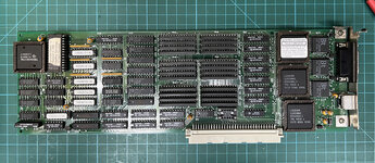
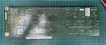
IMG_7275.JPG

IMG_7276.JPG

The card itself looks to be in good condition. No obvious damage and didn't see any obviously damaged traces either.

I pulled the ROM (v1.0). It's 16K and was inverted. After inverting it, the checksum checks out. So the ROM appears ok.

But I would have expected this card to have at least one oscillator, but there's none. There's a slot for one and it's empty. Newer versions of these cards had empty oscillator slots allowing the user to add one or more. But there's usually one soldered onto the board and this one does not have that.

I did find a picture of this card online and at least in that picture, it has a 64.0 MHz oscillator. I had a spare one so I installed it in the empty slot. Didn't help.

Checked the voltage lines coming into the card via the nubus connector and those are good. Given the card isn't even detected, need to put a scope on the nubus connector and see what happens during boot.
 

MacOSMonkey

Well-known member
Cool - original Spectrum/24. Make sure the pin 1 orientation of the oscillator is correct when you are trying it and that you are using a standard monitor - like SuperMac 19" 60Hz or Apple 13" with a known good sync-on-green cable.

The standard oscillators for that board (and also the Spectrum/8 Series II) were:
64.00 Mhz for 19" 60Hz 1024x768 (Sony Trinitron)
30.24 Mhz for Apple 13" 640x480
24.00 Mhz for Multisync 640x480 - maybe SuperMac or NEC (I forget -- check the docs or SuperVideo)
17.73 Mhz for PAL 576x768 (not exact broadcast standard...and there may have also been 1 other PAL Config...check SuperVideo)
14.31818 Mhz for NTSC 640x480 (not exact broadcast standard)
12.27 Mhz for Apple NTSC 640x480

...and it also supported custom timing modes using an oscillator of up to 64.00 Mhz, but YMMV.

Burn/verify a new 1.0 ROM, double-check the oscillator and check the Bt parts/scope the the Bt output. It may just be an artifact of the photo/lighting, but the board may look a little baked on the back side under the middle Bt453.
 

jmacz

Well-known member
It was the lighting. The area on the backside of the DACs look fine.

There should be at least one crystal installed right? For this card, did SuperMac ship it with a particular frequency or include multiple crystals and let the user pick one based on the monitor they are using?
 

MacOSMonkey

Well-known member
Yes - there needs to be a crystal installed. There are no clock synthesizers on the early boards. Those came later. I think Spectrum/24 originally shipped with 64.00Mhz oscillator installed on the board and a 30.24Mhz in the box. If users wanted to use NTSC, they could call in for a 14.31818Mhz oscillator (or one for PAL, etc.).
 

jmacz

Well-known member
Installed a 30.24MHz crystal which didn't help.

I used a nubus interposer that I made to observe the card. The ACK, TM0, and TM1 lines are stuck active (ie. low). These signals are coming from a SN74F534N flip flop (for the TM0/TM1) and a S74F367N buffer (for the ACK) and the traces to/from these chips are fine. The chips themselves physically look ok. Need to trace further.
 

MacOSMonkey

Well-known member
The interposer should be helpful. Anything directly connected to a NuBus line on the board could be ESD'd from handling (buffers, etc.), since people sometimes handle the NuBus connector from the bottom and touch (and maybe shock) the pins. It's an unknown. Also, if you have a PLCC puller, you could try pulling the TMS34061 and checking/carefully cleaning the pins and socket. Maybe there is some oxidation? (Be careful and don't bend the pins.) You have already pulled and verified the ROM, so maybe it is OK.

Otherwise, go back to basics:
- Start by checking for Power/Ground shorts without power -- as much as you can cover.
- Then put the board on the bench, add a probe ground hook (or alligator clip works too), carefully power it, check for shorts again and make sure all the parts have Power/Ground.
- Make sure the board is coming out of reset.
- Make sure the onboard oscillator is working
- Make sure the TMS3406 SYSCLK and VIDCLK are valid.
- Check to see if anything is hanging on the bus when the board is on the bench.
- If you have a logic analyzer, you could try wiring the bus, watch the behavior out of reset, look at address/data, R/W, etc. Start by looking at reset, then R/W, then maybe add the address and data lines, etc. You would probably want to trigger on POR, then watch the transactions.

It's just a thankless, stepwise, hardware debug process. You will eventually find the problem. :D If something is blown, there may be some parts challenges...or not.

For signal debug, refer to Designing Cards and Drivers. For example: /AD0, /AD1 high and /TM0, /TM1 low looks like a byte 0 write, but it may just be an error state and not be significant. See Chapter 3, Table 3-1 on p. 57 - 3rd Ed. for correlation.
 
Top