• Updated 2023-07-12: Hello, Guest! Welcome back, and be sure to check out this follow-up post about our outage a week or so ago.

Supermac Spectrum/24 Series III and Series IV Issues

Phipli

Well-known member
In the meantime, I think I may have found a few surface mounted capacitors and transistors that are bad. I'm getting suspect measurements from them via my multimeter. There's about 5 or so of them in the vicinity of the previous burnt fuse. Rest on the board return reasonable numbers.

Anyone know how to determine the specs of these surface mounted caps/transistors? They are using 1206 packages, but not sure how you're supposed to determine the specs as there are not distinguishable markings on them.
Can you photograph and point out which ones you suspect?

Where caps are just decoupling caps, between the power rails of a chip and in close proximity, the values are unlikely to be critical. Either a 100nF might do in that instance, or check what SuperMac used on your other card, or elsewher on this card.

The transistors will be labeled, even if it is cryptic.
 

MacOSMonkey

Well-known member
If it's really a 1206, it's probably just bulk capacitance, but I didn't think there were any 1206's on that board. Are you sure it's not an 0805 part? The majority of parts were 0805 or, maybe, 0603. SMT process from that era for the boards rarely (if ever) used 0402s. If you have a specific question about a bad part value that you can't measure, let me know and I can probably check one of my boards. Also, consider that the part value is probably going to be similar to other analogous SMT caps on the board. Likely values are .01uF, .1uF, 1uF and 10uF -- from bypass to bulk. You would look for a 50V X7R - hard to go wrong there. Specs are much better now vs. the early '90s.
 

jmacz

Well-known member
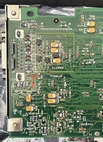
IMG_4441.JPG

The "F1" marking in red are the joints for the fuse (it's on the other side of the board). When I received the card, the 2A fuse that normally should be there wasn't there, and in its place was a 1.5A fuse that also looked damaged. I've since removed it and replaced with the proper 2A fuse. The fuse pins (again in red) connect to C120, R53, R52.

The yellow markings are where the ADV473KP110ES chip is.


Bottom Left Corner

R44
and R52 I already replaced as those were completely shot. All other resistors are in spec with their labeled ratings.

I am suspecting capacitors C4, C7, C120 for which I'm seeing either no continuity when testing for resistance or super high resistance (30M). Also RC4 (not sure what that is) which also has a super high resistance.

Also the transistors at Q1 and Q2 seem a bit suspect.. not sure if I'm thinking about it the right way. The other ones on the board are open when the power is off. However Q1 and Q2 seem to be closed with 10K resistance across the two pins (E/C?).


Top Left Corner

R19
I already replaced as it was shot. All other resistors are in spec. Also C5 and C10 (not in the picture -- it's on the top side of the board) also are showing no continuity during resistance measurements.
 

jmacz

Well-known member
If it's really a 1206, it's probably just bulk capacitance, but I didn't think there were any 1206's on that board. Are you sure it's not an 0805 part? The majority of parts were 0805 or, maybe, 0603. SMT process from that era for the boards rarely (if ever) used 0402s. If you have a specific question about a bad part value that you can't measure, let me know and I can probably check one of my boards. Also, consider that the part value is probably going to be similar to other analogous SMT caps on the board. Likely values are .01uF, .1uF, 1uF and 10uF -- from bypass to bulk. You would look for a 50V X7R - hard to go wrong there. Specs are much better now vs. the early '90s.

R44, R52, and R19 which I replaced were 1206 size packages, they measured 3.2mm x 1.6mm. The capacitors are the same physical size as the resistors and measure 3.2mm x 1.6mm as well so I believe they are 1206s?
 

MacOSMonkey

Well-known member
I will look for my board. What is going on with C6, C8 and RC5? Are those parts burnt or is it just an artifact of the picture? Also, if R44 and R52 were blown, you might be right to suspect Q1 and Q2.
 

jmacz

Well-known member
I will look for my board. What is going on with C6, C8 and RC5? Are those parts burnt or is it just an artifact of the picture? Also, if R44 and R52 were blown, you might be right to suspect Q1 and Q2.
C6, C8, and RC5 are good.. it's an artifact from the picture. Let me see if I can use something better than my phone for a higher resolution picture.
 

MacOSMonkey

Well-known member
It looks like Q1 is a 1AM transistor, which is an NPN 2N3094. Q2 appears to be the corresponding 2A transistor, which is a PNP 2N3906. The dark (reddish) stuff I was seeing is probably just adhesive from the SMT process. As for the ceramic caps, my best suggestion is to desolder one or more of them and check the values with a cap meter, etc. (as before, if you want to measure/check them, you have to remove them from the board). They are probably .1uf or .01uf, but just guessing. I will check a couple of them...or if you check (or have checked) them, please let me know.

The image below comes from the back of a 1992 Thunder/24 GX board. It should give clear part IDs for everything that is labeled.
PDQTransistors.png
 

MacOSMonkey

Well-known member
Yep - I was in a hurry - thanks for the swaperoo. Ugh - can't edit it - @moderator -- please change that text so that the post is correct.
 

jmacz

Well-known member
I tested all resistors using a multimeter and got reasonable resistance measurements except for a handful of them, and I replaced those with new resistors and so all the resistors are good now.

I tested the resistance on all the capacitors and found 8 of them which were suspect (super high resistance in the millions or my multimeter was saying it was open). I tested all the capacitors with my ESR meter as well and since I don't have the specs for the caps, I can't correctly interpret the results but my ESR meter was saying 7 of the capacitors had suspicious values, all 7 were part of the 8 I found with suspicious resistance measurements. What do I mean by suspicious for my resistance measurements? All the other caps were returning resistance values in the hundreds or thousands. These 8 were the only ones that were either open or in the millions.

So I pulled all 8 of these capacitors. And here are some of the measurements with the capacitor removed from the board. For each of these, note that I did try measuring both directions just in case.
  • C4 (bottom side) - 45nF reading (probably a 50nF), bad ESR, 30M+ resistance
  • C7 (bottom side) - 45nF reading (probably a 50nF), bad ESR, OL on resistance
  • C120 (bottom side) - 96nF reading (probably a 100nF), bad ESR, 20M+ resistance
  • C15 (bottom side) - 100nF reading, bad ESR, 20M+ resistance
  • C124 (bottom side) - 10nF reading, ESR meter says OPEN, 30M+ resistance
  • C10 (top side) - 50nF reading, bad ESR, OL on resistance
  • C5 (top side) - 1uF reading, good ESR, OL on resistance?? confused about this one
  • C13 (top side) - can't get a capacitance reading, ESR meter says OPEN, 20M+ resistance
I want to try replacing each of these capacitors but not sure if I fully trust the capacitance readings. Wish these things had identifiers on them. Not even sure what the significance of the colors on them are. Most of them are a light brown. Some are gray. Some are darker brown. Go figure. And I'm missing the reading on the C13 which obviously looks dead.

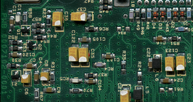
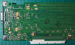
Also confused about the board markings ... resistors start with an R, and capacitors start with a C. Transistors look to start with a Q. And regular diodes begin with an L. The orange diodes (marked with a D) seem to be Zener diodes? But the ones I don't understand are the components labeled with an RC. If you look at my most recent high resolution picture, lower middle of the board, about an inch to the right of the monitor port, you will see RC6 and also an RC4. The RC6 clearly is labeled like a resistor. But RC4 is not labeled and looks like a capacitor. Huh??
 

jmacz

Well-known member
I have 1206 sized 100nF, 10nF, and 1uF capacitors (which if my readings are correct, cover C120, C15, C124, and C5. Unfortunately, I don't have a 47nF (which looks to be what I need for C4, C7, and C10). I may have to put this one on hold for a bit until I have another Mouser.com order as it would suck to pay $10 for shipping on just this.

Still have no idea what's going on with RC4 vs RC6.

And not sure what to do about C13 which is clearly dead thus can't get a measurement on the capacitance.
 

MacOSMonkey

Well-known member
L designations are for inductors. Diodes are D. RC could be a resistor or cap -- or maybe a ceramic resistor -- or maybe a fuse. You will have to check it. A cap should have very high (infinite) resistance -- if there is low resistance across a cap (removed from a PCB), it is probably bad. Also, be aware that it is possible to overheat caps and destroy them. So, if you end up removing small caps, it is often better just to replace them. In terms of values, you may be able to figure out some info if you can find a manufacturer reference design in the databook for the device (usually always included) -- like the DAC book. It may help.
 

jmacz

Well-known member
RC could be a resistor or cap -- or maybe a ceramic resistor -- or maybe a fuse.

The fuses are labeled with an F. I just find it odd as one of the RCs looks like a resistor and is marked as such. The other looks like the other ceramic capacitors on the board. So curious what the difference is between R, C, and RC.

A cap should have very high (infinite) resistance

Yeah, but I had thought in practice, they should read in the high thousands, tens of thousands, hundreds of thousands.. I had thought if it's at the other extreme, in the high double digit millions, something's also wrong? I had thought someone told me that once, but maybe I'm wrong.
 

MacOSMonkey

Well-known member
For the RC part -- it's possible that it is part of an adjustable RC network and the RC designation was a way to flag it vs. other standard discretes. The design supported multiple SKUs with some alternate components. So, it could be a multi-function site - but just guessing. If you want to know the specific function of what is installed in that specific board, you can remove it from the board and measure it with your cap/ohmmeter -- that should answer the question.

For caps, the resistance across the terminals should be in the meg range (basically open -- or very high resistance) or unmeasurable (infinite) -- and you can't measure them in-circuit. They have to be off the board...at least in a black box diagnostic process. If you want to test resistance behavior, you can check it on new, known-good caps of different types -- non-polarized ceramic, tantalum, polarized axial, electrolytic, etc. I have a bunch of new parts around here - I could make a table for you. Or, if you have new parts there, the results should be the same.
 

jmacz

Well-known member
Yeah, I have some new parts. I will try building up that info.

Trying to figure out what to do about C13 which is off the board and definitely dead so can't take a measurement. Not much additional information on this card online that I can find so far.
 
Top