the CPU walking the bus is a really good sign -- a lot of things have to be going right for that to happen. UK6 is the video ROM, right? pins 2-10, 21, and 23-25 are just the address lines (i.e., inputs) so i wouldn't expect swapping the chip to affect anything there. i'm assuming that you're only observing that behavior with the ROM present? that plus the lack of startup chime seems consistent (imo) with the CPU having trouble accessing memory (which could be caused by any number of things).
You are using an out of date browser. It may not display this or other websites correctly.
You should upgrade or use an alternative browser.
You should upgrade or use an alternative browser.
Macintosh SE/30 logicboard recreation (thread revival)
- Thread starter Bolle
- Start date
ThisDoesNotCompute
Active member
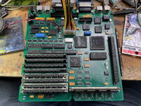
Another thing that's crossed my mind is the chips -- some of them were populated at the factory when the board was made, and the rest are a mix of transplanted and NOS parts. I've attached a high-res photo of my board, maybe someone can spot something wrong? (It turns out the pin probes I ordered for my multimeter are backordered, so it'll be a while yet before I can test the connections between the PLCC chips and their sockets.)
Attachments
ThisDoesNotCompute
Active member
Yeah, C12 is intentionally crooked because JLCPCB didn't do a very good job packing the boards, and a couple of them had their caps torn off in shipping. Both pads for that one are completely gone, so I had to get creative with fitting the replacement cap.
daanvdl
Well-known member
Dear all,
For those who are interested, I have a few (unpopulated) SE/SE30 analog boards left from my SE analogboard recreation project.
https://airtalk.shop/product/macintosh-se-and-se-30-analog-board-recreation-630-0147-c
These boards are electrically fully functional but have one silkscreen error (W2 is labeled as W1). Furthermore no issues.
I know Bolle has mentioned that "Certain low power ATF16V8B don't work." I assume this refers to the ATF16V8BQL. Has anyone tried any of the half or quarter-power GAL16V8s or PALCE16V8s? Just wondering if it might be possible to reduce the heat generated by the PALs.
I can confirm GAL16V8D-15LPs work well. Haven't tried the QPs or any of the PALCEs yet.I know Bolle has mentioned that "Certain low power ATF16V8B don't work." I assume this refers to the ATF16V8BQL. Has anyone tried any of the half or quarter-power GAL16V8s or PALCE16V8s? Just wondering if it might be possible to reduce the heat generated by the PALs.
Tested some GAL16V8D-10QPs today and they also appear to work well. These are actually lower power than ATF16V8B-15PUs according to the datasheets; 45mA typ. / 55mA max. for the GALs vs. 55mA typ. / 95mA max for the ATFs, so these may actually run marginally cooler than the ATFs.I can confirm GAL16V8D-15LPs work well. Haven't tried the QPs or any of the PALCEs yet.
My board doesn't have a socket at UH7, so I am only testing the 5 DIP chips.
Bolle
Well-known member
I just recently was testing PALCE16V8H-15 for the DIP chips and while it works fine on a stock board it will fail once an accelerator is added.
Traced it down to the video logic being too slow to assert /DSACK. Keeping -15 in place for everything but replacing UE6 with something faster seems to knock the timing back into place.
Tried with PALCE16V8H-10 for all the DIPs too and it obviously was just fine that way as well.
Traced it down to the video logic being too slow to assert /DSACK. Keeping -15 in place for everything but replacing UE6 with something faster seems to knock the timing back into place.
Tried with PALCE16V8H-10 for all the DIPs too and it obviously was just fine that way as well.
naruse
Well-known member
hey guys,
So I am trying to set up an order of PCBs for the logic board of @Bolle's SE/30 logic board in JLCPCB.
I have downloaded the board files from https://github.com/TheRealBolle/SE30/blob/main/Board Files/mlb_reloaded_r4_2023-12-09.zip (notice the r4) and when I get asked to upload the BOM and CPL files (Which I got them from https://github.com/TheRealBolle/SE30/tree/main/BOM and pick & place files) (the files are r2)
I get his error on JLCPCB.
Could this be because the versions are different? (r2 and r4). thoughts?

Also, as a Followup question -- is there any BOM CPL files for the top? -- I can imagine the sockets for the various surface mounted ICs + through hole ones (the ones one can get) and the couple of diodes available
So I am trying to set up an order of PCBs for the logic board of @Bolle's SE/30 logic board in JLCPCB.
I have downloaded the board files from https://github.com/TheRealBolle/SE30/blob/main/Board Files/mlb_reloaded_r4_2023-12-09.zip (notice the r4) and when I get asked to upload the BOM and CPL files (Which I got them from https://github.com/TheRealBolle/SE30/tree/main/BOM and pick & place files) (the files are r2)
I get his error on JLCPCB.
Could this be because the versions are different? (r2 and r4). thoughts?
Also, as a Followup question -- is there any BOM CPL files for the top? -- I can imagine the sockets for the various surface mounted ICs + through hole ones (the ones one can get) and the couple of diodes available
Last edited:
finkmac
NORTHERN TELECOM
there is no newer bom/pick and place fileset, it's just the board itself that changed. try downloading them again.
there's a topside BOM some youtuber made, but i do not recommend that. you'd have to coordinate jlcpcb ordering non-stocked items and also more importantly the cost to assemble both bottom AND top is significantly pricier.
also you're in canada right. you're gonna get hit hard with duties.
there's a topside BOM some youtuber made, but i do not recommend that. you'd have to coordinate jlcpcb ordering non-stocked items and also more importantly the cost to assemble both bottom AND top is significantly pricier.
also you're in canada right. you're gonna get hit hard with duties.
naruse
Well-known member
I am,also you're in canada right. you're gonna get hit hard with duties.
 damn
damn Thanks for the replies! -- I'll be attempting that again hopefully tonight
brayne
Well-known member
I just joined the SE/30 reloaded build club, so I thought I would share a couple of my experiences. I received my board from @ThisDoesNotCompute (thanks Colin!) but it wasn't one of the boards he got made up with the wrong components under the RAM slots. It's a Rev 03 board, so it required the little bodge wire to get rid of the graphic artefacts.
At first testing I was getting a sad Mac chime, but I was getting audio and video (simasimac pattern) so I was pretty sure the fix would be straightforward. After lots of testing, I was getting all sorts of intermittent issues. Sometimes it would startup fine, other times it would give a sad Mac chime, other times it would be silent.
Fast forward many hours and I finally found the cause. It was a faulty RAM slot. I salvaged the RAM slots from an old SE/30 and even though I cleaned them, I guess there were some issues with the contacts, or maybe something was cracked. I removed the Bank A slots and replaced them with some newer slots I salvaged from a Mac IIsi, and all of a sudden it came good.
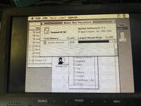
The other issue I had was an odd one, but I found the cause. The SE/30 would not boot from SCSI, but it would boot from the floppy drive. However, when I booted via floppy (using a System 7.0.1 image with a Floppy Emu) the SCSI drive mounted and I could access it. So SCSI was working, it just wouldn't boot from SCSI.
I was able to run Snooper, and the PRAM/RTC chip failed its test. I whipped it out and replaced it with another, and bingo! The SCSI booted perfectly. So if you ever have an SE/30 that won't boot from the SCSI drive, but the SCSI still passes all tests, check out the RTC chip, that might be the problem.
It's been a frustrating exercise, knowing that my assembly was fine, but my stooooooopid decision to use old, plastic RAM SIMMs gave me no end of trouble.
A huge thanks to @Bolle for creating the SE/30 board in the first place, and for always replying to my annoying messages with support.
Another huge thanks has to go to @WillJac for his help during my build livestreams.
And anyone with a keen eye will notice I soldered the PDS slot backwards. Check twice and solder once.
At first testing I was getting a sad Mac chime, but I was getting audio and video (simasimac pattern) so I was pretty sure the fix would be straightforward. After lots of testing, I was getting all sorts of intermittent issues. Sometimes it would startup fine, other times it would give a sad Mac chime, other times it would be silent.
Fast forward many hours and I finally found the cause. It was a faulty RAM slot. I salvaged the RAM slots from an old SE/30 and even though I cleaned them, I guess there were some issues with the contacts, or maybe something was cracked. I removed the Bank A slots and replaced them with some newer slots I salvaged from a Mac IIsi, and all of a sudden it came good.
The other issue I had was an odd one, but I found the cause. The SE/30 would not boot from SCSI, but it would boot from the floppy drive. However, when I booted via floppy (using a System 7.0.1 image with a Floppy Emu) the SCSI drive mounted and I could access it. So SCSI was working, it just wouldn't boot from SCSI.
I was able to run Snooper, and the PRAM/RTC chip failed its test. I whipped it out and replaced it with another, and bingo! The SCSI booted perfectly. So if you ever have an SE/30 that won't boot from the SCSI drive, but the SCSI still passes all tests, check out the RTC chip, that might be the problem.
It's been a frustrating exercise, knowing that my assembly was fine, but my stooooooopid decision to use old, plastic RAM SIMMs gave me no end of trouble.
A huge thanks to @Bolle for creating the SE/30 board in the first place, and for always replying to my annoying messages with support.
Another huge thanks has to go to @WillJac for his help during my build livestreams.
And anyone with a keen eye will notice I soldered the PDS slot backwards. Check twice and solder once.
Attachments
croissantking
Well-known member
It's a Rev 03 board, so it required the little bodge wire to get rid of the graphic artefacts.
Back when I was diagnosing the fault with the artefacts, it seemed like only myself and one other person (@Garrett B) were afflicted with this problem. For the longest time it led me to believe there was something wrong with my own assembly or parts selection. Since discovering the fix, seems like a lot of Rev03 and earlier builds are being affected and needing that bodge wire. But it could just seem that way as there are a lot more Reloaded builds out there now.
And anyone with a keen eye will notice I soldered the PDS slot backwards. Check twice and solder once.
You know, you can actually just lever the plastic part of the PDS connector off the pins, then turn it round and snap it back in. I have done this and as long as you’re gentle I am confident it won’t damage anything.
@Bolle I noticed a new revision (R5) was being uploaded to your GIT repo. Do you have any changelog available?
Ooh, interesting!
croissantking
Well-known member
The pads on the two large PLCCs are longer now… especially on the 68882 the pads of the default 68882 device that came with Eagle can be troublesome to solder by hand.
Yes, the 68882 is tricky as well as the 26LS30s I always found.
daanvdl
Well-known member
Thx. A welcome patch!The pads on the two large PLCCs are longer now… especially on the 68882 the pads of the default 68882 device that came with Eagle can be troublesome to solder by hand.
Similar threads
- Replies
- 69
- Views
- 63K