Bolle
Well-known member
I recently finished testing on the final (so far) working revision of the SE/30 board.
Below is my initial post from before the site crash on how everything started:
All things on the "left to do" list had been worked out before the site crash.
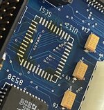
Just recently I found the time to finally order a batch of revision 2 boards with the SCSI blooper fixed and PLCC32 ROM sockets added.
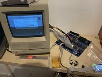
Now just look at this beauty:
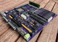
Passed all tests, no bodge wires needed and already has been running 3 days straight now without any hiccups.
Board files, reverse engineered PAL files and BOM available on github:

 github.com
Many thanks go to...
@joshc for putting together the BOM
@cheesestraws for supporting me with reverse engineering the PALs
@Siliconinsider for making those beautiful die shots of the GLUE https://www.siliconpr0n.org/archive/doku.php?id=bercovici:apple:344s0602-a - who's going to give recreating that one a go now?
@Kai Robinson for putting together pick and place files (also found in the github)
and finally @GeekDot for bugging me into starting with this project in the first place and working on the (not yet working) in system ROM flashing software when using the PLCC32 ROM sockets (more on that later - probably)
I'll clean up the github over the next days and add some more descriptive information.
Below is my initial post from before the site crash on how everything started:
Just like I promised when teasing everyone in the SE logicboard thread here we go with the build-log/information exchange/everything thread on the SE/30 logicboard replacement PCB.
The plan to redraw the available SE/30 schematics in Eagle has been in my head now for quite some time. It wasn't the task of having to redraw everything that kept me off, but I genuinely hate creating new devices in Eagle, so there goes that.
Luckily @GeekDot kept bugging me about it and thankfully took over the job of creating Eagle devices for all the custom Apple ICs on the SE/30 board.
This got me started and things quickly went down from there... a month ago I began copying the Apple schematics to Eagle. With most of the devices available this went through in a breeze.
Only two days later I was already taking measurements on one of my SE/30 boards to arrange components and get them as close as possible to the original
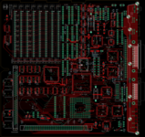
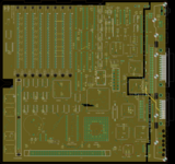
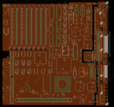
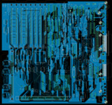
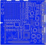
Another week in (not doing much else than drawing blue and red lines all day long) and still somewhat surprised that things went through so quickly I was basically done with a first revision:
Most components found their place in exactly the same spot as on the original board - unless it was useful to move them around a little bit. The RTC for example to make some space for a CR2032 battery holder.
The battery is the only component I replaced with something that's not on the original. (yes I know, 72pin RAM, a single 16bit VRAM IC, accelerators, network cards, grayscale, and a PPC built right in - no)
Goal for me was to set a baseline and verify the Apple schematics are even correct and would result in a running board before thinking about modernization efforts.
One major advantage of re-doing the whole routing of the board is that everything can be made to fit into 4 layers, instead of the 6 layers the original board had. This is cutting costs dramatically.
So on it goes with ordering boards...
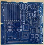
It took two weeks to turn this:
into that:
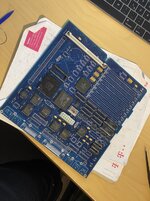
and a few hours later to find myself here:
Only a few components missing to get her powered up for the first time - I went without any RAM to see if it actually does anything at all before bothering to solder in SIMM sockets.
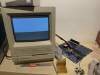
So a few more bits soldered down, a deep breath and the flip of a switch later:
SUCCESS! It turns on at least and I got video. I seriously didn't expect it to even do that.
No chimes of any sort though - would have expected the slow chimes of death because there's no RAM.
At least the screen image is what is to be expected if there's no RAM installed which was a good thing.
I took a break here, got some food for dinner, took a shower and while doing the latter it struck me... to get sound you need the headphone port to be present, because of the switch that's in there and connects the internal speaker to the amplifier.
So back to the workbench... two little jumpers on the headphone ports solder pads and there we go - slow death chime was there indicating RAM failure.
It was time to go to bed at that point but I couldn't have slept anyways. I got a donor board, moved over the RAM muxes, control signal buffer and missing address line resistor arrays, installed 4 SIMM sockets.
I put in some RAM, hooked the board up again and couldn't believe my eyes when I was looking at that flashing question mark.
Well past bedtime a SCSI and floppy port went onto the board, back on the testbed with FloppyEmu and a hard drive connected...
I sh*t you not the damn thing was booting from floppy - first board revision, rushed through copying the schematics, board layout, routing, putting it together... and it just boots.
Not a single jumper wire (spoiler: yet!)
Notice how there's no HD showing up? This is where rushing through things strikes back.
I copy-pasted the data lines to the SCSI IC from the nearby SCC - not noticing that they were sorted different in the original schematics. D24-31 on one and D31-24 on the other IC.
End result: the data lines to the SCSI controller were reversed. Nothing that can't be fixed though.
Popped the SCSI controller off again, cut the data lines and installed jumper wires.
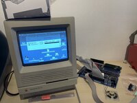
And that's how I ended up here:
The board now has a few hours of runtime on it and seems to be rock solid so far.
Couldn't notice any differences from an original.
Left to do:
-test the serial ports (haven't done that yet because I totally never use serial ever)
-test external Floppy and SCSI ports
-chassis fitment
-runtime runtime runtime
The SCSI blooper has been corrected already for the upcoming rev 2 of the board.
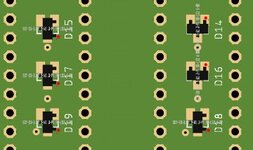
A few SMD pads will be added here and there for the fuses, SCSI Term power diode - those were through hole only for simplicity.
And a few more images to drool over:
All things on the "left to do" list had been worked out before the site crash.
Just recently I found the time to finally order a batch of revision 2 boards with the SCSI blooper fixed and PLCC32 ROM sockets added.
Now just look at this beauty:

Passed all tests, no bodge wires needed and already has been running 3 days straight now without any hiccups.
Board files, reverse engineered PAL files and BOM available on github:
GitHub - TheRealBolle/SE30: Macintosh SE/30 logicboard recreation
Macintosh SE/30 logicboard recreation. Contribute to TheRealBolle/SE30 development by creating an account on GitHub.
Many thanks go to...
@joshc for putting together the BOM
@cheesestraws for supporting me with reverse engineering the PALs
@Siliconinsider for making those beautiful die shots of the GLUE https://www.siliconpr0n.org/archive/doku.php?id=bercovici:apple:344s0602-a - who's going to give recreating that one a go now?
@Kai Robinson for putting together pick and place files (also found in the github)
and finally @GeekDot for bugging me into starting with this project in the first place and working on the (not yet working) in system ROM flashing software when using the PLCC32 ROM sockets (more on that later - probably)
I'll clean up the github over the next days and add some more descriptive information.

