• Updated 2023-07-12: Hello, Guest! Welcome back, and be sure to check out this follow-up post about our outage a week or so ago.

Macintosh SE/30 logicboard recreation (thread revival)

croissantking

Well-known member
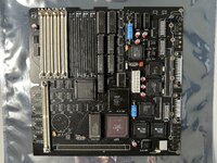
I'm a little unclear on exactly how to implement the fix. The photo above of the factory bodge wire shows it going from (a test point apparently connected to) pin 14 of UG7 to under the socket on UI6. Where does it go? And would that bodge be applicable to the Reloaded board?

This is how I've done one of my boards. You're bodging pin 6 of UE7 to pin 3 of UI6, and cutting the trace that leads to UE7 from the GLUE. It's exactly the same (logically) as the Apple factory bodge, but adjusted physically because the Reloaded board is routed differently.

IMG_4771.jpg
 

Bolle

Well-known member
As i had 14 boards to add this fix to, I made a video for others to see.
Did all of them actually have problems? Technically there's no need to modify boards that don't show the problem.

I experimented a bit with one of my boards and could actually reproduce the issue when using TI 150ns VRAM chips. Any of the other VRAM chips I have around seem to fall into the setup time window that still works when using /NUBUS instead of /AS to generate the VRAM /RAS signal.

I just uploaded the files for a Rev4 board to github.
 

croissantking

Well-known member
I experimented a bit with one of my boards and could actually reproduce the issue when using TI 150ns VRAM chips. Any of the other VRAM chips I have around seem to fall into the setup time window that still works when using /NUBUS instead of /AS to generate the VRAM /RAS signal.

Do the 150ns chips work fine when using /AS?

I just uploaded the files for a Rev4 board to github.

Thank you for the credit on the board. You made my day.
 

Bolle

Well-known member
Do the 150ns chips work fine when using /AS?
They are pulls from original boards, so I'd say yes. Didn't get around to doing the modification on one of my assembled reloaded boards... just swapped around the VRAM chips real quick because I had them socketed on one board.
 

ymk

Well-known member
The /ECS signal fires ahead of /AS, but Apple didn't see a use for it, so it leads to nowhere.
 

Melkhior

Well-known member
The /ECS signal fires ahead of /AS, but Apple didn't see a use for it, so it leads to nowhere.
In fairness to Apple, /ECS is pretty useless. It doesn't qualify other signals (/AS mostly does, /DS for data... sometimes) and it can be asserted and then de-asserted without any actual cycle occurring. It's basically just a warning that the CPU might do an useful cycle soon...

@croissantking Congratulations on finding the issue! Bad luck that we all looked at the Apple schematics instead of Bomarc's...
 

Phipli

Well-known member
Congratulations on finding the issue! Bad luck that we all looked at the Apple schematics instead of Bomarc's...
Not quite how I'd phrase it 😆 The bomarc schematics have many errors and are... Less intuitive. Using the Apple Schematics was the right thing to do. They'll have been checked. Just there was a change after the leaked version that doesn't impact all boards, and so was missed during extensive testing by several forum members.
 

WillJac

Well-known member
Did all of them actually have problems? Technically there's no need to modify boards that don't show the problem.

I experimented a bit with one of my boards and could actually reproduce the issue when using TI 150ns VRAM chips. Any of the other VRAM chips I have around seem to fall into the setup time window that still works when using /NUBUS instead of /AS to generate the VRAM /RAS signal.

I just uploaded the files for a Rev4 board to github.
only a few of my previous order boards showed issues but I replaced the PAL and video RAM and went away but to be safe, I feel better to apply the fix to them all. I have had boards that, on my bench, worked perfect but when the owner got it back, it was giving problems with artifacts and had to get the board returned and fixed. Thanks for the rev 4 release and already have some them on order. Perfect timing!!!
 

Chopsticks

Well-known member
Absolutely fascinating and also impressive to read/learn through all this testing and debug work being done to find out the core issue.

I was finally in the position to order some boards yesterday, green with gold plating etc

Not wanting to hijack this thread or anything but if there’s anyone in Australia that wants an pcb or two that’s pre-populated with the bottom side passives I’ll have a couple spare in the next couple weeks I’ll be happy to part with at cost price if that’s helpful to anyone. I don’t mind holding onto the extra couple boards but I know they cost a bit to get made so just wanted to offer in case it’s helpful to anyone who’s also in the same position as me with not having a lot of spare cash to get 5 made at a time and say only needs one board etc.

Again just offering in case it’s helpful to any locals in my region of the world
 

croissantking

Well-known member
hi all, just wanted to share my (by all appearances) successful build. I got my first successful boot (off of a real floppy, no less) last week after spending a couple of frustrating weeks tracing out address and data lines trying to figure out why i was still getting a Simasimac pattern on startup.

View attachment 63599


I still had some hardware issues at this point (FPU connectivity, mostly) but the feeling i got the first time i flipped the switch and got a proper gray background and cursor made the previous frustrations totally worth it :) at some point i will probably write up some of the debugging steps i went through to get here in more detail in case it would be helpful to others.

Also wanted to say thank to everyone who has posted in this thread previously -- while i didn't post here looking for help myself, i don't think i would have been able to figure this out without the previous discussion here.
A little late to respond, but well done on a successful build (hopefully still working)!
 

igowen

Member
A little late to respond, but well done on a successful build (hopefully still working)!
thanks! it is very much still working, and i've got the Bolle trinity (ethernet+040+cache) in there speeding things up. i also picked up a radius video card for the IIsi that i'm trying to fit (it works but i haven't tried to get the case back on yet, and i need to build the internal cable to hook it up to the video port on the ethernet panel).
 

ThisDoesNotCompute

Active member
I made significant progress in building my own Reloaded board recently, and just today tried to power it on for the first time. I connected it to a known-good SE/30 chassis, using known-good RAM and ROM SIMMs. To my chagrin, it just displays a Simasimac pattern -- so the lights are on but nobody's home. I'm reasonably certain with my solder work, but as we all know the PLCCs are not fun. I've attached photos of both the board as I've gotten it so far, as well as the pattern on screen. Any hints on where to start with troubleshooting?
 

Attachments

  • reloaded-board.jpg
    reloaded-board.jpg
    3.8 MB · Views: 53
  • simasimac.jpg
    simasimac.jpg
    1.7 MB · Views: 53

croissantking

Well-known member
I made significant progress in building my own Reloaded board recently, and just today tried to power it on for the first time. I connected it to a known-good SE/30 chassis, using known-good RAM and ROM SIMMs. To my chagrin, it just displays a Simasimac pattern -- so the lights are on but nobody's home. I'm reasonably certain with my solder work, but as we all know the PLCCs are not fun. I've attached photos of both the board as I've gotten it so far, as well as the pattern on screen. Any hints on where to start with troubleshooting?
Do you get chimes of death?

You’ll need to solder in the 3.5mm audio jack in order to check this - the internal speaker header won’t work without it. As an alternative to soldering in the jack, you could close the pads on the PCB, adjacent to where the jack fits which close the circuit for the header.
 

croissantking

Well-known member
To expand a little more on my thinking, if you are able to hear the death chimes you would know that the CPU is operational and talking to the ROM - in which case I’d suspect a possible issue with the RAM circuitry.

You may also hear a normal boot chime in the case that there is something wrong with the video circuitry. You can get a simasimac in this scenario too. This happens with the Video ROM removed, for example.

I suspect your soldering is good too but just to be sure, I’d beep out the connections on each pair of adjacent legs of the PLCC chips that you hand soldered, just to make sure there aren’t any hidden bridges, particularly on the GLUE chip.

Otherwise, could there be a compatibility issue with any of the replacement PLCC chips you’ve used? I know you asked about those VIA chips a little while ago. If you had some other donor parts to try out, that would be the most ideal thing.

Equally do you know that all the donor parts are good?
 

Daniël

Well-known member
Otherwise, could there be a compatibility issue with any of the replacement PLCC chips you’ve used? I know you asked about those VIA chips a little while ago. If you had some other donor parts to try out, that would be the most ideal thing.
I don't think they would be incompatible, the VLSI VIAs are 65C22s as well, which is a fairly standardized chip AFAIK.
 

ThisDoesNotCompute

Active member
Only a few of the PLCCs are NOS replacements -- the FPU, UK11/UK12, and the SCSI chip are from UTSource, while the rest are transplants from a donor board. The donor was battery bombed so I wasn't able to test it. All of those are socketed so connection issues are unlikely, but I can certainly check the soldered PLCC chips for any shorts. I did keep all of the PLCCs from the donor, so if something does suggest one of the replacements is at fault, it's easy enough to swap out. Some of the DIP chips are NOS as well, I'll have to check which ones, though I was careful to match exact part numbers when ordering them.

When I go to check for shorts on the chips I'll also add the audio jack and see if there's a chime.
 

ThisDoesNotCompute

Active member
Updates:

--No chime through the audio jack
--It's the same simasimac pattern regardless of whether the ROM SIMM is installed
--No shorts on UI8. UH7 has a short between pins 10-11 but this is expected (and confirmed on another board)
--I tried swapping the FPU, SCSI chip, UB10 and UB11 with the original parts, but no change
 

igowen

Member
one thing to try would be to pull the ROM and check the address lines with a scope -- if the CPU is running you would expect to see A(2) through A(31) being pulled high/low (square wave, basically) in exponentially decreasing frequency as the CPU is trying to find some code to run. if that's not happening, i would check the clock generation circuit(s) -- IIRC UH7 is heavily involved there, and that's the chip i had the most trouble with soldering properly due to its physical location on the board.

also i would recommend making sure all your socketed PLCC chips are making good contact with their sockets (especially the ones that were pulled from the old board) -- i had multiple chips that had legs that needed to be bent outward ever so slightly to make contact.
 

ThisDoesNotCompute

Active member
That's the path I've started to go down with troubleshooting. Over the past week I've confirmed a few more things:

--I tested all the connections to/from the ROM slot, CPU, UI8 and UH7 for continuity and they all check out. If there's a problem with those, it's not due to the soldering.
--The CPU does indeed walk the bus when the machine is powered on.
--I'm getting abnormal readings from chips like UD8 and UK6. On UD8, I get nothing on pins 4 and 12, pins 7 and 9 show square waves even when the system is not being reset, and pin 13 always stays high. On UK6, pins 2 through 7 all stay high, pins 8 through 13 and 15 through 19 all stay low, and pins 20 through 25 all stay high.
--I swapped the video ROM chip with a known-good one, no difference.

I have a set of pin probes for my multimeter on order, so I can check continuity of the PLCCs with their sockets -- the chips not making good contact is definitely a theory worth pursuing.
 
Top