PB170
Well-known member
The problem…
A bit of background/history:
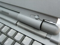
Almost immediately after I purchased my PowerBook 170 back in 2001, two unfortunate accidents happened.
After only using it once or twice, a crack in the insulation at the tip of the AC plug (a problem affecting the first version of PB1XX adapters) caused the fuse to blow on the motherboard, resulting in a repair at a local Apple reseller and the purchase of a new, second hand power adapter, which in total cost me more than I had just spent on the computer.
Then, shortly after I had the computer up and running again, I decided to try and see if I could remove a small, annoying hair that was stuck somewhere between the layers in the middle of the display. After carefully removing the front bezel, I made the devastating mistake of trying to adjust the display slightly, resulting in two of the screw posts breaking completely free from the back.
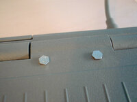
Some time later, I decided to try to fix the problem by drilling four small holes through the rear part of the display housing* and running new screws and bolts through it to secure the display to the hinge, covering the bolts with the same type of rubber covers used over the screws on the front to retain the original look. This slight modification turned out very successful, and has held together well through more or less daily use for two decades all up to the present. Considering how some of the screw posts inside the machine fall apart more or less on their own, I'm amazed that the plastics has held together for this long.
An old photo of the fix:
However, recently, things started to change…
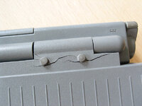
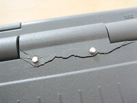
Small cracks in the plastics began to appear in 2020. Back then, I repaired them with JB Weld, which has held together well. (Thanks by the way for recommending this amazing product – incredibly strong, not to mention it matches the color of the PowerBooks perfectly!) However, during the past few months, new, more severe cracks started to appear (in new places), and at this point many of them were pretty much beyond repair if the plastics were also going to support the hinge screws like before**. So I needed a more future proof solution.
After a lot of thinking, considerations, and careful measurements, I settled on a metal extension design for the hinges to completely free the display housing from the hinges and instead secure the rear part of the housing at the top of the display where the stress is much lower:
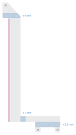
One consideration in the design was to avoid having the metal extensions go over any components on the display PCB, to avoid the risk of damage to the PCB in the future. That meant that they would have to follow the sides of the PCB. This, however, would mean that the stress on the extensions would be focused on the narrow, horizontal part near the hinges. To prevent the metal from twisting during use, I designed the extensions out of 1.2 mm steel, which seemed to be the sweet spot (1.0 mm steel seemed a bit too weak, and pure iron which I first considered was much too soft). I also made the vertical parts much wider than I originally had planned in order to minimize the length of horizontal part. The pieces weigh in at 44 g each, so quite acceptable, although a bit more than I first had in mind.
The height of the extensions means the display will move 1.2 mm closer to the bezel (which is actually very nice since there's quite a bit of room in the original design and it's nice with a closer fit). To make the display sit flat, I added two washers between the display and the two lower screw post (not pictured).
Finished extensions:
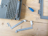
(Bonus point that they kind of look like giraffes or dinosaurs )
)
Some photos of the work in progress:
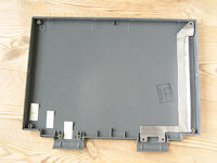
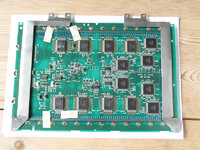
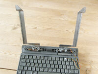
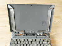
Somewhat surprisingly, the tolerances between the hinges and the display housing are quite precise, so despite careful measurements, I had to extend/elongate the top screw holes slightly to allow for some fine tuning of the position of the rear plastic part.
Aside from this minor adjustment, the design turned out successful, and I now have a solution where the plastic housing is completely separate from the hinges, and the display is held up entirely by the extensions rather than the plastic housing!

Such an incredible and relieving feeling to finally not have to worry about over- or under-tightening the screws, and instead secure them tightly entirely around metal parts!
Final assembly:
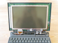
Details of the bent parts:
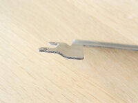
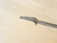
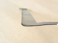
I include the final, revised design in Adobe Illustrator 9 format here if anyone is interested.
A few notes:
Some additional details and photos:
Hinge modifications:
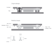
Metal plate design:
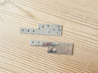
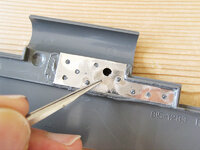
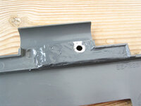
Note: I made a mistake with the design here. The plates extend too far towards the hinge which means that the bezel doesn't fit properly. This is fixed in the design I've uploaded (in the version I had already made, I solved it by filing down the excess, as shown below.)
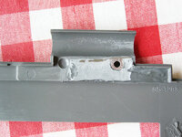
Revised design:

Extra padding over the video connector:
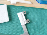
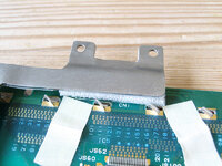
Final assembly:
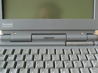
To sum up, after a whole long month of confinement to my desk at home, my trusty and beloved PowerBook is finally mobile again

* Around the same time, I received a PowerBook 140 from a colleague which, unlike my PowerBook 170, had a minor dent in the rear part of the display housing, so I decided to use it for the modification and spare the one from my own PowerBook in case the modification wouldn't work.
** What I ended up doing here was to discard the damaged back and revert to the original one from my PowerBook 170, while I chose to repair the less severe cracks in the front bezel with JB Weld and reinforce it with metal plates (wouldn't want to have my PowerBook 170 say "PowerBook 140" on the front ). While I didn't mind the look of the modification I made back in 2001, it's nice to have the original look back, and also to get rid of the aforementioned dent in plastics


A bit of background/history:
Almost immediately after I purchased my PowerBook 170 back in 2001, two unfortunate accidents happened.
After only using it once or twice, a crack in the insulation at the tip of the AC plug (a problem affecting the first version of PB1XX adapters) caused the fuse to blow on the motherboard, resulting in a repair at a local Apple reseller and the purchase of a new, second hand power adapter, which in total cost me more than I had just spent on the computer.
Then, shortly after I had the computer up and running again, I decided to try and see if I could remove a small, annoying hair that was stuck somewhere between the layers in the middle of the display. After carefully removing the front bezel, I made the devastating mistake of trying to adjust the display slightly, resulting in two of the screw posts breaking completely free from the back.
Some time later, I decided to try to fix the problem by drilling four small holes through the rear part of the display housing* and running new screws and bolts through it to secure the display to the hinge, covering the bolts with the same type of rubber covers used over the screws on the front to retain the original look. This slight modification turned out very successful, and has held together well through more or less daily use for two decades all up to the present. Considering how some of the screw posts inside the machine fall apart more or less on their own, I'm amazed that the plastics has held together for this long.
An old photo of the fix:

However, recently, things started to change…
Small cracks in the plastics began to appear in 2020. Back then, I repaired them with JB Weld, which has held together well. (Thanks by the way for recommending this amazing product – incredibly strong, not to mention it matches the color of the PowerBooks perfectly!) However, during the past few months, new, more severe cracks started to appear (in new places), and at this point many of them were pretty much beyond repair if the plastics were also going to support the hinge screws like before**. So I needed a more future proof solution.
After a lot of thinking, considerations, and careful measurements, I settled on a metal extension design for the hinges to completely free the display housing from the hinges and instead secure the rear part of the housing at the top of the display where the stress is much lower:

One consideration in the design was to avoid having the metal extensions go over any components on the display PCB, to avoid the risk of damage to the PCB in the future. That meant that they would have to follow the sides of the PCB. This, however, would mean that the stress on the extensions would be focused on the narrow, horizontal part near the hinges. To prevent the metal from twisting during use, I designed the extensions out of 1.2 mm steel, which seemed to be the sweet spot (1.0 mm steel seemed a bit too weak, and pure iron which I first considered was much too soft). I also made the vertical parts much wider than I originally had planned in order to minimize the length of horizontal part. The pieces weigh in at 44 g each, so quite acceptable, although a bit more than I first had in mind.
The height of the extensions means the display will move 1.2 mm closer to the bezel (which is actually very nice since there's quite a bit of room in the original design and it's nice with a closer fit). To make the display sit flat, I added two washers between the display and the two lower screw post (not pictured).
Finished extensions:

(Bonus point that they kind of look like giraffes or dinosaurs
Some photos of the work in progress:


Somewhat surprisingly, the tolerances between the hinges and the display housing are quite precise, so despite careful measurements, I had to extend/elongate the top screw holes slightly to allow for some fine tuning of the position of the rear plastic part.
Aside from this minor adjustment, the design turned out successful, and I now have a solution where the plastic housing is completely separate from the hinges, and the display is held up entirely by the extensions rather than the plastic housing!
Such an incredible and relieving feeling to finally not have to worry about over- or under-tightening the screws, and instead secure them tightly entirely around metal parts!
Final assembly:

Details of the bent parts:


I include the final, revised design in Adobe Illustrator 9 format here if anyone is interested.
A few notes:
- The current design of the extensions will only work with the PowerBook 170 display (and maybe other active matrix displays in the series). It will have to be modified to work with passive matrix PowerBooks.
- The design requires the complete removal of the screw posts on the rear part of the housing and the protruding parts around the screw holes on the inside of the front bezel, as well the addition of metal plates to the front bezel to be able to secure the new screws to hold the bezel in place (not needed for the hinge extension to work, but the bezel will stand out a bit around the hinges without them). (See the photos/drawings below)
- Since the rear part is no longer affixed to the hinges, there's a small gap between the back and front parts of the housing on bottom side. Not a big problem, although it could allow for dust to enter the hinges more easily. This would probably be pretty easy to fix by connecting the two parts around the bottom center somehow, but I'll save that for a future project.
- The side of the extensions facing the PCB is covered with insulating tape to prevent shorts.
- Extra padding added on the left extension near the hinge to prevent it from coming in contact with the solder points for the video connector at any time in the future.
- The uploaded designs are revised and corrected following the adjustments I made, but do make your own measurements just to be sure if you decide to go ahead and build your own
Some additional details and photos:
Hinge modifications:

Metal plate design:


Note: I made a mistake with the design here. The plates extend too far towards the hinge which means that the bezel doesn't fit properly. This is fixed in the design I've uploaded (in the version I had already made, I solved it by filing down the excess, as shown below.)

Revised design:

Extra padding over the video connector:


Final assembly:

To sum up, after a whole long month of confinement to my desk at home, my trusty and beloved PowerBook is finally mobile again
* Around the same time, I received a PowerBook 140 from a colleague which, unlike my PowerBook 170, had a minor dent in the rear part of the display housing, so I decided to use it for the modification and spare the one from my own PowerBook in case the modification wouldn't work.
** What I ended up doing here was to discard the damaged back and revert to the original one from my PowerBook 170, while I chose to repair the less severe cracks in the front bezel with JB Weld and reinforce it with metal plates (wouldn't want to have my PowerBook 170 say "PowerBook 140" on the front
Attachments
Last edited:
