David Cook
Well-known member
I've recently recapped three PowerBook 100 computers, along with adding some upgrades. Nothing earth-shattering to report. Here are the things I documented.
I replaced the LCD electrolytic capacitors with tantalum capacitors. I didn't want to use aluminum electrolytic capacitors again, due to leakage. Some people have warned against ceramics (frequency or voltage issues?). I simply bent the capacitor leads and clipped them short.
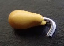
I then held the capacitor in place with sticky tack when soldering. After that, I gently bent the capacitor down. It might seem like they are sitting high, but they actually fit just fine.
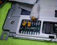
I did not have the same luck with using tantalum capacitors on the inverter board. It worked -- but made an obnoxious high-pitched whining sound. I swapped in aluminum polymer, which worked without noise. I could not find a 15 uF aluminum polymer, but a 22 uF seems to work as a substitute. Height is a real issue on the inverter board. 6 mm high capacitors fit, but 7 mm high capacitors do not.
Of the three laptops, only one screen is perfect.
One of the screens has the purple / red mark of physical damage. The topmost mark is from the trackball. Not sure what caused the other mark. (Chucking a gold plated Cross pen at the screen upon seeing his Apple stock crash in mid-1993?)
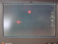
Here is a close up of the trackball damage. It appears to be in the layers above the actual pixels.

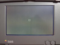
The other screen has half of a black line due to a loose connection on one of the driver chips. Theoretically, this is fixable. Haven't tried.
Bodges
One of the PowerBooks is revision 11. The other two are revision 12. Revision 11 has quite a few bodges on the backside of the motherboard.
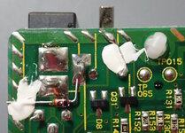
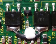
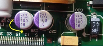
On revision 11, capacitor C38 is in the same orientation as C30 and C37. In revision 12, C38 is rotated 90 degrees. (Photo below is after recapping with aluminum polymer and tantalum capacitors.) By the way, most of the original capacitors have a much higher voltage rating than necessary. See the schematic to determine the actual voltage these capacitors are exposed to. For example, the 1 uF 50V capacitors were common. It doesn't mean that 50V ratings were necessary for the board; that was just the usual rating in that size package.
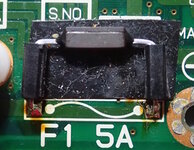
Revision 11 has long leads on the fuse. The leads and body are insulated with respect to the motherboard. Why so big?
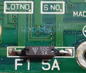
Here is the revision 12 fuse. Also notice a change in the silkscreen at top.
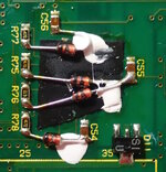
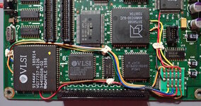
Revision 12 does not have the bodges on the back. But, it does have massive pulldown resistor bodges. My second revision 12 board does not have the bodges. Someone theorized on a different thread that these bodges were applied after sale as part of a recall, as opposed to in the factory.
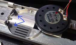
Only one of the laptops had a pair of adhesive fuzzies on the speaker mount. I assume these are to reduce vibration and improve sound. If they were for speaker retention, you'd think they would just use tape or hot glue.
Memory
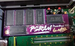
The PowerBook 100 comes with 2 MB of RAM. One of my PowerBooks had a 2 MB upgrade card. The other had a 4 MB upgrade card. I've switched them all to modern 6 MB upgrade cards (for a total of 8 MB). If you have a junk 170 or 140 with a short memory card installed, it might be a compatible 2 MB or 4 MB upgrade.
Disk
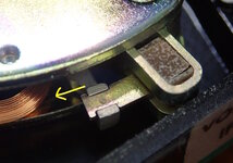
On my PowerBooks, one of the hard drives works. The other two are Conner CD-2025 with stuck heads. If you open the drive and nudge the rear of the head arm away from the rotten bumper, you can probably get the drive working long enough to backup the contents.
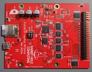
I replaced the two stuck drives with ZuluSCSI laptop RP2040 solid-state drives from Rabbit Hole Computing. They work perfectly. However, the memory card comes blank. So, be sure to configure a drive on the card before installing it into the laptop.
Battery
Rather than recapping the external power supply brick, I just bought a modern replacement from eBay. It is smaller and it works fine.
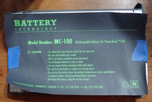
One of the batteries was a Battery Technologies MC-100. (Sorry about the post teardown photo.) If you peel off the sticker, you'll find four screws holding on the aluminum lid.
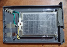
Inside is a slightly small set of lead-acid cells. Given the screw-on lid, this is a nice shell for hacking your own replacement cells.
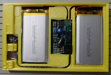
I ordered a replacement battery from eBay. It comes in a 3D printed case that fits snugly. The lid is hot glued on. Inside, you'll find some decent 3600 mAh lithium rechargeable batteries with protection circuitry.
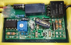
The relay-based charging circuit is described in a different forum post. It is a custom board, rather than off-the-shelf boards stuck together.
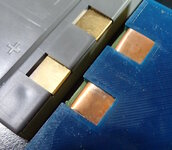
My only concern is the material used for the battery terminals. These appear to be plain copper, rather than brass or tin-plated. I think the copper will oxidize.
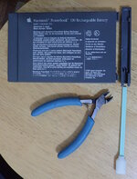
Even though the 3D printed case fits snugly in the battery slot, it is preferable to reuse the cap from an official Apple battery to close the slot. I struggled to get the cap off by hand. So, I trimmed the handle of a cleaning swab to make a cap removal tool.
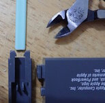
Taper the ends of the plastic handle to wedge open the retaining clips. Then the battery cover will slide off.
- David
I replaced the LCD electrolytic capacitors with tantalum capacitors. I didn't want to use aluminum electrolytic capacitors again, due to leakage. Some people have warned against ceramics (frequency or voltage issues?). I simply bent the capacitor leads and clipped them short.

I then held the capacitor in place with sticky tack when soldering. After that, I gently bent the capacitor down. It might seem like they are sitting high, but they actually fit just fine.

I did not have the same luck with using tantalum capacitors on the inverter board. It worked -- but made an obnoxious high-pitched whining sound. I swapped in aluminum polymer, which worked without noise. I could not find a 15 uF aluminum polymer, but a 22 uF seems to work as a substitute. Height is a real issue on the inverter board. 6 mm high capacitors fit, but 7 mm high capacitors do not.
Of the three laptops, only one screen is perfect.
One of the screens has the purple / red mark of physical damage. The topmost mark is from the trackball. Not sure what caused the other mark. (Chucking a gold plated Cross pen at the screen upon seeing his Apple stock crash in mid-1993?)

Here is a close up of the trackball damage. It appears to be in the layers above the actual pixels.

The other screen has half of a black line due to a loose connection on one of the driver chips. Theoretically, this is fixable. Haven't tried.

Bodges
One of the PowerBooks is revision 11. The other two are revision 12. Revision 11 has quite a few bodges on the backside of the motherboard.


On revision 11, capacitor C38 is in the same orientation as C30 and C37. In revision 12, C38 is rotated 90 degrees. (Photo below is after recapping with aluminum polymer and tantalum capacitors.) By the way, most of the original capacitors have a much higher voltage rating than necessary. See the schematic to determine the actual voltage these capacitors are exposed to. For example, the 1 uF 50V capacitors were common. It doesn't mean that 50V ratings were necessary for the board; that was just the usual rating in that size package.

Revision 11 has long leads on the fuse. The leads and body are insulated with respect to the motherboard. Why so big?

Here is the revision 12 fuse. Also notice a change in the silkscreen at top.

Revision 12 does not have the bodges on the back. But, it does have massive pulldown resistor bodges. My second revision 12 board does not have the bodges. Someone theorized on a different thread that these bodges were applied after sale as part of a recall, as opposed to in the factory.

Only one of the laptops had a pair of adhesive fuzzies on the speaker mount. I assume these are to reduce vibration and improve sound. If they were for speaker retention, you'd think they would just use tape or hot glue.

Memory
The PowerBook 100 comes with 2 MB of RAM. One of my PowerBooks had a 2 MB upgrade card. The other had a 4 MB upgrade card. I've switched them all to modern 6 MB upgrade cards (for a total of 8 MB). If you have a junk 170 or 140 with a short memory card installed, it might be a compatible 2 MB or 4 MB upgrade.

Disk
On my PowerBooks, one of the hard drives works. The other two are Conner CD-2025 with stuck heads. If you open the drive and nudge the rear of the head arm away from the rotten bumper, you can probably get the drive working long enough to backup the contents.

I replaced the two stuck drives with ZuluSCSI laptop RP2040 solid-state drives from Rabbit Hole Computing. They work perfectly. However, the memory card comes blank. So, be sure to configure a drive on the card before installing it into the laptop.

Battery
Rather than recapping the external power supply brick, I just bought a modern replacement from eBay. It is smaller and it works fine.
One of the batteries was a Battery Technologies MC-100. (Sorry about the post teardown photo.) If you peel off the sticker, you'll find four screws holding on the aluminum lid.

Inside is a slightly small set of lead-acid cells. Given the screw-on lid, this is a nice shell for hacking your own replacement cells.

I ordered a replacement battery from eBay. It comes in a 3D printed case that fits snugly. The lid is hot glued on. Inside, you'll find some decent 3600 mAh lithium rechargeable batteries with protection circuitry.

The relay-based charging circuit is described in a different forum post. It is a custom board, rather than off-the-shelf boards stuck together.

My only concern is the material used for the battery terminals. These appear to be plain copper, rather than brass or tin-plated. I think the copper will oxidize.

Even though the 3D printed case fits snugly in the battery slot, it is preferable to reuse the cap from an official Apple battery to close the slot. I struggled to get the cap off by hand. So, I trimmed the handle of a cleaning swab to make a cap removal tool.

Taper the ends of the plastic handle to wedge open the retaining clips. Then the battery cover will slide off.

- David

