• Updated 2023-07-12: Hello, Guest! Welcome back, and be sure to check out this follow-up post about our outage a week or so ago.

PowerBook Duo battery replacement

Trash80toHP_Mini

NIGHT STALKER
I never had a chance to call today, too many fires to put out, but I got a lot done on several fronts, IRL and here as well. :approve:

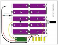
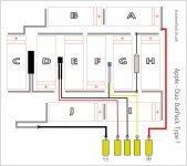
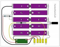
It's now a little after 4AM and I've pried the cells of the BTI MC-Duo2300 battery just far enough apart to do a circuit diagram. It's late because I couldn't let it go, I also translated the asymmetrical FatBarH into the very neat little 2x5 array of cells. Amazingly enough, all the solder connections for the components happen at the outside ends, leaving a clean center line for the five springs mounted between the pairs of cells.

I stopped by the Shack and picked up three more battery packs to cannibalize, but I'll only need two in addition to the one in the pictures. Since the two intervening components of the circuit are wired up to the separate termination ends from the packs and I need two separate termination ends to attach the battery to the contacts, I only need two of the very cool joint plates.

For now I'm treating the PIC board as a black box, only showing the four wires connected to the three pads on the bottom. After I get the two diagrams done in Illustrator, I'll probably have a go at doing a detail box for the PCB that shows all the traces and the components they connect. Maybe you sorcerers can divine the meaning of this friggin' mess from the diagrams and PCB layout . . .

. . . |) zzzzzzzzzzzzzzzzzzzzzzzzzzzzzzzzzzzz


Trash80toHP_Mini

NIGHT STALKER
FrankenPack.03.2p.jpg

Any weird squiggly lines just show excess wire so I can flop the components back inside the case between the cells.

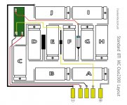
Anybody know sources of good diagrams of the Types I-III Apple battery packs? Now that the library of parts is built in Illustrator, variations on this theme will be a cinch. I'm going to do my other BTI Battery layout as well as the stock layout of the BTI MC-Duo2300.

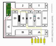
The only difference between the two layouts is that the component connected to the yellow wires is in between Cells D & F in the FrankenPack, the real deal has it nestled betwixt cells E & F.

Now what the heck can that PIC board be reading and doing about it?

edit: the thin red(?) wire hooked up between the rocket ship with the blue band and the PCB would be the orange wire in my pics of the unit, :-/

edit again: |) time for bed, it seems I've typo'd the label on cell "H" as well. ::)


bigmessowires

Well-known member
Very nice diagram! The component connected to the yellow wires should be the thermistor. The other two are both fuses, I'm pretty sure. Maybe one is fast blow and one is slow blow.

That looks identical to how my Type I battery is configured, with two exceptions:

- it has the "transistor-looking" ID chip instead of the little green circuit board

- there's no connection between the fuse and the ID chip (the left-most red wire in your diagram)

My Type III battery is configured the same as well, with these exceptions:

- the cells are physically laid out in an H pattern, instead of 5 rows of two cells (but the electrical connections are the same)

- instead of the fuse that looks like a bullet, it has a something that looks like 1 cm square piece of paper with a tiny something inside it


Trash80toHP_Mini

NIGHT STALKER
Thanks, big! [:)] ]'> Now that I've ripped this graphic out of that great howto.pdf I'll be doing all the variations available. I'm hoping it'll be easy enough to see what values for whatever it is that the PIC is shuffling around in there. Knowing what feed what disinformation output is required to hoodwink the the Power Manager into charging whatever capacity cells as BTI did could make it easy for to use any cells we decide now or to use in the future. [}:)] ]'>

DuoBatDiag.jpgHopefully I can get this printed at work to markup and then doink it into Illustrator this evening. :approve:

If anyone can post the real identities of the components of the standard battery as labeled in this diagram, that would help me a lot in doing the rest of the diagrams and in updating this one.


Trash80toHP_Mini

NIGHT STALKER
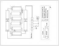
This diagram seemed totally different from the two Duo Batteries that I have opened up, I thought maybe mine were a different type at first. I think I was just tired. Now it looks to me like he's showing the center pair of components flipped out tho the outside of the pack as I did in my first diagram. The Batteries aren't set up with the terminal matching the pattern in my packs, Maybe he thought it was a clearer presentation?

Dunno, I'm much more tired than I was when I started . . .

Duo_Howto.pdf_Diagram.2p.jpg

. . . but playing in Illustrator and GraphicConverter are very soothing activities for me. [:)] ]'>

This is the pre-FrankenPack AA Hack, stock config of my later model, standard size, high capacity BTI Duo Battery.

BTI_MC-Duo2300_2p.jpg

The main difference that jumps out at me is the four count of discrete components in the Apple Bat, are reduced to only three in the BTI Bat, with that PIC card as an intelligent substitute? Dunno . . . over my head . . . I'll just keep doin' my thing: making pretty pictures and breaking things.

I'll be doing the Apple Bat and the other (oversized) BTI Bat diagrams before I start cutting things apart. [}:)] ]'>


bigmessowires

Well-known member
The main difference that jumps out at me is the four count of discrete components in the Apple Bat, are reduced to only three in the BTI Bat, with that PIC card as an intelligent substitute?
I count four components in both batteries: two fuses, a thermistor, and either a PIC or an ID thingy that looks like a transistor.


Trash80toHP_Mini

NIGHT STALKER
The little blue thingie must be part of the PCB in the BTI Pack, it's not present otherwise. The "Paper thing that looks like it has something in it" or some such appears to me to be the Tab -> Flex Circuit connection.

Apple - BatPack.2p.jpg

I was counting the PIC PCB as an anomaly, not as an active component per se, it's just a tad more complex than the ApplePack's little blue thingie. [:eek:)] ]'>

After I print out the Apple BatPack Diagram, I'm going to try to deduce the logical function of the anomalous "Black Box" from the differences in components and I/O at the contacts between brands.


Trash80toHP_Mini

NIGHT STALKER
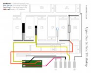
Here's the grayed out version of my Apple Bat (Type?) with the markup of the differences from the BTI pack.

Apple Pack-BTI Markup.2p.jpg

It looks to me like no signal comes from, or goes back to, the Power Manager on those three contacts without going through the BTI PIC Card were that unique orange input line comes into play somehow.

Methinks the PIC on this PCB is a congenital liar. [}:)] ]'>

file.php


edit: I should have noted that the THIN black lines are the deleted/contrasting traces for comparison purposes.

The heavy gray lines are the RED WIRE and thick flex cable power transmission lines.


Trash80toHP_Mini

NIGHT STALKER
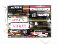
Phase 1 complete: FrankenPack™

FP-PhaseOne.2p.jpg

Now the real work begins! [:)] ]'>

Synopsis of the gobbledegook posted above:

After having documenting the 4/5 A Cell MC-Duo2300, I've disassembled its innards and fitted them into the empty shell along with the stand-in standard AA cells.

file.php


The documentation the new FrankenPack™ cell/circuitryconfiguration for the off the shelf AA NiMH Cells above as well:

file.php


The documentation for utilizing cannibalized parts from three CrapShack 2 x AA Battery Packs ( approx. $2 ea.) is on the previous page.

file.php


I'll be contacting BTI regarding the proper capadity cells for the two versions of their High Capacity Batteries. But for now I'll just go ahead and buy another pair of four packs of the 2450mAh Energizers to match the most recently purchased rechargeables I have on hand just to see what kind of run times I can get with those! [}:)] ]'>

I still need to Diagram the BTI MC-T4, but there's no rush on that, its circuitry is very likely identical to the MC-Duo2300.


Trash80toHP_Mini

NIGHT STALKER
THX, me too! What do you make of that BTI markup diagram I did over the Apple Battery circuit diagram? Is it clear enough? Suggestions?

I've got a very nearly destroyed Apple battery that I think I'll turn into a makeshift breadboard so I can hook up a prototype using whatever standard battery holders I can scavenge around here. Might as well make sure that devious lil' PICamajigger is still in working order. Doing a dry run of everything without waiting for the serious hackage to be completed seems the thing to do.

First: Is my previous post a clear enough explanation of the silliness it's taken to get to this point? I can edit in changes, more pics a/o verbiage as needed to make it sound like "English."

Second: I think I've finally figured out a way to make reassembly/breakdown a snap. [;)] ]'>


Trash80toHP_Mini

NIGHT STALKER
Now that I've got a Visible/MinimalistDuo™ RevII for torturing with alligator clips I've got a question for you. Are the wires on the CrapShack holders really heavy enough to do the job? The new four-packers have much thinner gauge wires than my older packs and the wires on those are more lightweight than the Tabs and especially the Red Wire in the ApplePacks.

Wire gauge advice for when I start hanging batteries on the lid? :?:


Trash80toHP_Mini

NIGHT STALKER
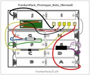
Hey, big, if you get a chance, could you (or anyone else for that matter) compare the FrankenBat™ diagram to the Beta Prototype for error checking? I'd appreciate it, My vision is blurry and I need to get some sleep.

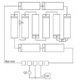
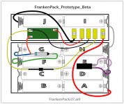
OK, then, I've got wire, I picked up another double holder and found a pair of Quad AA Holders. I'm using a pair of each cut down to as close an approximation as I can get to the final packaging of the FrankenPack™ design. Doing it this way puts all three components in the 4/8 Cell section where they belong, one column in the 2/4 casing yields the other two Cells and free cubic to house the PIC Board and the five contact terminals (shown as battery contacts) for the wolligator-wire-up to the new Duo TestBed's prongs.

FrankenPack_Proto_Beta.2p.jpg

FrankenPack.03.2p.jpg

BTI_MC-Duo2300_00.jpg

Might as well put the original layout I did of the MC-Duo2300 before i took it apart. Can anyone spot any circuit errors in comparing between the three?

:?:


bigmessowires

Well-known member
I think it's time to stop make Illustrator diagrams, and just put some cells in your homebrew battery and try it out! :)

The green board is wired differently in your third diagram. That green board has three pads on it in an L shape. If the top of the L is pad 1, the corner is pad 2, and the foot of the L is pad 3, then your diagrams work out this way:

Diagrams 1 and 2

pad 1: battery terminal 2

pad 2: battery terminal 3

pad 3: voltage from four cells (about 5V)

Diagram 3

pad 1: voltage from four cells (about 5V)

pad 2: battery terminal 3

pad 3: battery terminal 2


Trash80toHP_Mini

NIGHT STALKER
:lol: Maybe so, but I'm NOT an electronics guy by any stretch of the imagination. I'm a visual thinker/hardware hacker only, so doing an electron plumbing diagram in Illustrator is a necessary tool for me, not a reason for procrastination. Having you back-stop me on the wiring setup is a big help. I have several Duos, several standard Apple batteries and therefore several chances to get that right.

Conversely, I have only one (probably good ) PIC board from which to vent the dreaded MAGIC SMOKE!!!!!!!!!!!!!! :O

Such being the case, I'm currently assembling the external battery pack built into the Minimalist Duo Mk.II case in order to test the acid etched backup PIC board first!

I'm trying to be methodical and to clearly diagram every known Duo battery configuration. I need a pic of the innards of a complete Type I battery from someone, BTW.

Is the latch mechanism arrangement the only way to easily tell the Types apart?

_____I have:

_____________spring loaded short button Model Number: M1499

_____________long button, slide integrated latch Model Number: M7782

Are there any additional configurations besides the AA Cell Type I Battery?

. . . and now to pore over the diagrams for the error you noted, I can't easily process your .TXT :I


bigmessowires

Well-known member
That now looks the same as the 3rd of the three diagrams from your previous post. But I've lost track of what all these diagrams represent. :)


Trash80toHP_Mini

NIGHT STALKER
The third (bottom of the three) diagram is a graphical representation of BTI MC-Duo2300 configuration as pictured below the revised diagram.

The larger, original Pic of the MC-Duo2300 is on the previous page.

I've bought enough holders to build two external battery packs into the lid of the new minimalist Duo testbed. The first one will use standard Apple Components with AAs in the same configuration as the revised FrankenPack™ Beta Prototype diagram.

As a matter of fact, I'm hoping to be run time testing the standard Apple charging circuitry against the, PIC Board enhanced, BTI high capacity recharging hack doing, using exactly the same 10 AA Cells in each ProtoPack for the tests. [}:)] ]'>

Yesterday I spent wrasslin' to get the LCD out of the badly borken-n-crumbling Duo Lid. Right now it is just mounted the front bezel and hinge assy. with no back/top. I need to epoxy a new brass bolt insert in to repair the top of the original busted up lid.

It was fun! ;D


Trash80toHP_Mini

NIGHT STALKER
That now looks the same as the 3rd of the three diagrams from your previous post. But I've lost track of what all these diagrams represent. :)
Maybe the progression of diagrams is way confusing. They're all labeled for identity and filename. I've been working toward making a final post with the diagrams of all three Duo Bats from Apple and my two BTI Bats all together. The ProtoPacks won't be in there to avoid confusion. I hope such a post will enable future hackers to proceed more easily in their projects. Schematic of what's happening electrically would be much appreciated, I can knock those out in AI as well, that's fun! [;)] ]'>

Could you please do a rough sketch of what your Type I battery circuitry was before you moved everything around and give me the model number? :?:

If someone could identify the model Numbers of all three Apple Bats that would be a big help in labeling the diagrams. I think I've previously posted the model numbers for Types II & III, but I'm not sure which is which.

We're getting there, first I'm building the Apple Duo Type X ProtoPack in the lid. The Battery holder assemblies I'm doing simultaneously and testing the Apple pack to make sure that works before trying vent the Magic Smoke from either of my two PIC Boards in the revised BTI Beta ProtoPack. [:)] ]'>

I'm planning on using screw down barrier strips for strain relief of the cable, that shouldn't pose any electrical problems should it?

I'm planning on using some ATX power extension Cables for the hookup. I'll be soldering the power lines to the vertical internal tabs of the MoBo contacts.

I'll be adding three contacts for ADB, along with just enough to break serial and EtherNet of the Duo TestBed's hull for future hacks. plug will hang from the left side of the Duo, with socket on each of the external battery packs so I can use an extension cable to hook either pack up to the Duo for power and the rest of the signals will be terminated to a stock Crapshack PCB, probably with header connections and/or hardwired sockets.

Could the extra wiring a/o screw down barrier strip cause any electrical signal or power transmission problems? :?:

 
Top