• Updated 2023-07-12: Hello, Guest! Welcome back, and be sure to check out this follow-up post about our outage a week or so ago.

Macintosh SE/30 logicboard recreation (thread revival)

ace192

New member
I have an LC which is dead. Not sure if its the TDK supply or the mainboard. I need to look at some point. I'll do some searching on the forum for the LC stuff. Thanks for the heads up!
 

GutBomb

Member
Thanks so much to Bolle for this project. It's been really fun to rebuild my SE/30 on this new board. It's been a great opportunity to learn.

That being said, I'm having a lot of trouble and if someone could point me in the right direction I would really appreciate it.

Let me start off by saying I'm pretty new to projects this deep and I'm still learning how to use an oscilloscope so I'm probably going to get some terms wrong.

Background: I got an SE/30 on ebay in march for cheap knowing it was a battery-bombed one just to see if I could fix it. the battery bomb was mild and after cleaning the board, bodging a couple traces on the back, replacing the ROM SIMM, and reflowing everything on the top side I was able to successfully boot in and everything appeared to work fine. I put 128MB of RAM in it and outside the case it was fine, but the RAM was too tall to slide the board in the regular way, so i bent the left side of the chassis out a tiny bit so I could directly place the board where it belongs in the chassis and then bent the left side of the chassis back into place to hold the board. at this point i started getting bomb errors whenever anything would bump my desk. I pulled the board out of the case again and tested by poking it in various points and consistently get bomb errors whenever it was even slightly moved. So I guess I cracked the board or something when I was wrenching it back into the case :(

I set it aside while I ordered replacement parts (IC sockets, RAM and ROM slots, etc) and harvested parts from the old board while I waited for the Bolle SE/30 board to arrive. The only things I had major trouble removing was the GLUE chip and the CPU. I had to use way more heat for more time than I was comfortable with for the GLUE and have wondered if I messed something up in there. I broke a pin off of the CPU as I was desoldering it, so ordered a replacement from ebay (a 33mhz part)

The board I ordered had PLCC sockets preinstalled for UK12, UK11, UJ11, UI12, UG12, UE10, and UI5. The bottom side was fully pre-populated and the top side had everything pre-populated aside for the through hole components, UD12, UH7, UI8, and UL11.

I cleaned all of my harvested parts and either socketed or soldered them to the new board, soldered in sockets for all of the through-hole ICs and resistor packs and brought all of that stuff over. I took pictures of my old board before I removed any parts to make sure that when I placed them in the new board they were going to the right places, and have triple checked that they are all in the right spots.

Unfortunately I just get the no chime Simasimac of the gray with the middle 3rd of the screen looking borked variety. I tested my harvested FPU in a different machine and it's okay, nowhere else to test the CPU.

From reading I've seen that I should remove the ROM (and the RAM? I have tried it with and without with no difference) to see if it walks the bus. The way I assume I'm supposed to do this is put my oscilloscope probe on to pin 4 in the ROM SIMM slot and fire the machine up. I should see a square wave there, and then just go up through the address lines to see square waves of increasing length as I go along. (I hope that's correct)

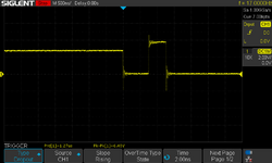
Unfortunately this is what I see on pin 4 (A2) and I just don't get anything on any of the other address lines:

SDS00001.png

I captured that by going to "single" on my scope and then resetting the machine while on that pin. If I'm interpreting that correctly that looks like it attempts to start doing the square wave pattern but then it just stops. when I try the same on any of the other address lines they all just stay low. For pin 4 it is low while I hold the reset button, goes up to about 3ish volts when I let go, then it does that one pulse at 5 volts and then just stays low after that.

I have toned out everything (all pins to all destinations) in the 2 matrices at the end of elemenoh's redrawn schematics and it all checks out okay. I've checked every single leg on every socket to make sure the chip is making contact with the socket on the correct pin and that there aren't any shorts, and there's no problem there either. I checked that all of the preinstalled chips were making contact with the board and there are no bridges there and everything was fine there too. I also checked the underside of the board to make sure there were no bridges with my mutimeter on every single through hole point but no problems there either.

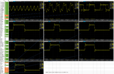
So, I am at a loss, and given how much trouble I had with the GLUE chip I decided I'd see what's going on with it with the scope so I mapped out the whole thing here, in hopes that maybe someone might find something off with it, or be able to steer me in the right direction as to what to look at next.

GLUE chip.png

Sorry this post is so dang long. I just really want to get this working, and I'm having a lot of fun learning about this stuff.

edit: for clarity, when I have RAM in the machine I am using 4MB of RAM while I test. The RAM works fine in my SE. I also tried using the SE/30 board with my SE analog board/power supply/CRT and it behaves exactly the same. The SE/30 analog board/power supply/CRT also work fine with my SE board)
 
Last edited:

CircuitBored

Well-known member
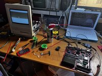
I was finally able to get my SE/30 Reloaded board to work properly today. I checked every single trace, reflowed the whole thing twice, and was just about to give up when I realised that I hadn't tried reseating the CPU yet. It was a complete hail Mary, but lo and behold!

IMG_6650.jpeg

I'm not exactly sure what to blame. My money is on the socket itself given that it was likely quite old stock.

Also: yes, that is a tiny hammer on my desk.
 

zigzagjoe

Well-known member
I was finally able to get my SE/30 Reloaded board to work properly today. I checked every single trace, reflowed the whole thing twice, and was just about to give up when I realised that I hadn't tried reseating the CPU yet. It was a complete hail Mary, but lo and behold!

I'm not exactly sure what to blame. My money is on the socket itself given that it was likely quite old stock.

Also: yes, that is a tiny hammer on my desk.
So that's how you reseated the CPU :)
 

croissantking

Well-known member
I was finally able to get my SE/30 Reloaded board to work properly today. I checked every single trace, reflowed the whole thing twice, and was just about to give up when I realised that I hadn't tried reseating the CPU yet. It was a complete hail Mary, but lo and behold!

View attachment 58827

I'm not exactly sure what to blame. My money is on the socket itself given that it was likely quite old stock.

Also: yes, that is a tiny hammer on my desk.
Congrats. I suppose that one of the pins may not have been making good contact? It does happen.
 

croissantking

Well-known member
@CircuitBored You will have to run it for a bit and verify there are no other issues. All three of my reloaded boards have intermittent graphical issues that I haven't fixed yet. What was your reasoning for socketing the GLUE chip but not the other PLCCs?
 

CircuitBored

Well-known member
@CircuitBored You will have to run it for a bit and verify there are no other issues. All three of my reloaded boards have intermittent graphical issues that I haven't fixed yet. What was your reasoning for socketing the GLUE chip but not the other PLCCs?

The board is currently in the hands of its new owner (my brother) and will be getting a thorough testing once I've cleared up some space in my (currently) moderately hellish tech space. All the basics are working well, though. SCSI, floppy drive, sound, and ADB are all working great. The only thing we haven't verified so far is serial.

I socketed the GLUE because it was the only donor part that I wasn't confident would work, as it was badly blackened and crusty. Sure enough, it did not work and I ended up using one from a IIcx. Also, Bolle advises that cramming the board with PLCC sockets can create as many issues as it solves, as it essentially doubles up the amount of possible circuit breaks. PLCCs that were previously soldered on have to be carefully refinished to get a reliable connection and even that's not a guarantee. Also, sockets are expensive and I was trying to build the reloaded board as cheaply as possible. Removing the sockets from the BOM took about £70 off the order price when I bought all the bits.
 

WillJac

Well-known member
Thanks so much to Bolle for this project. It's been really fun to rebuild my SE/30 on this new board. It's been a great opportunity to learn.

That being said, I'm having a lot of trouble and if someone could point me in the right direction I would really appreciate it.

Let me start off by saying I'm pretty new to projects this deep and I'm still learning how to use an oscilloscope so I'm probably going to get some terms wrong.

Background: I got an SE/30 on ebay in march for cheap knowing it was a battery-bombed one just to see if I could fix it. the battery bomb was mild and after cleaning the board, bodging a couple traces on the back, replacing the ROM SIMM, and reflowing everything on the top side I was able to successfully boot in and everything appeared to work fine. I put 128MB of RAM in it and outside the case it was fine, but the RAM was too tall to slide the board in the regular way, so i bent the left side of the chassis out a tiny bit so I could directly place the board where it belongs in the chassis and then bent the left side of the chassis back into place to hold the board. at this point i started getting bomb errors whenever anything would bump my desk. I pulled the board out of the case again and tested by poking it in various points and consistently get bomb errors whenever it was even slightly moved. So I guess I cracked the board or something when I was wrenching it back into the case :(

I set it aside while I ordered replacement parts (IC sockets, RAM and ROM slots, etc) and harvested parts from the old board while I waited for the Bolle SE/30 board to arrive. The only things I had major trouble removing was the GLUE chip and the CPU. I had to use way more heat for more time than I was comfortable with for the GLUE and have wondered if I messed something up in there. I broke a pin off of the CPU as I was desoldering it, so ordered a replacement from ebay (a 33mhz part)

The board I ordered had PLCC sockets preinstalled for UK12, UK11, UJ11, UI12, UG12, UE10, and UI5. The bottom side was fully pre-populated and the top side had everything pre-populated aside for the through hole components, UD12, UH7, UI8, and UL11.

I cleaned all of my harvested parts and either socketed or soldered them to the new board, soldered in sockets for all of the through-hole ICs and resistor packs and brought all of that stuff over. I took pictures of my old board before I removed any parts to make sure that when I placed them in the new board they were going to the right places, and have triple checked that they are all in the right spots.

Unfortunately I just get the no chime Simasimac of the gray with the middle 3rd of the screen looking borked variety. I tested my harvested FPU in a different machine and it's okay, nowhere else to test the CPU.

From reading I've seen that I should remove the ROM (and the RAM? I have tried it with and without with no difference) to see if it walks the bus. The way I assume I'm supposed to do this is put my oscilloscope probe on to pin 4 in the ROM SIMM slot and fire the machine up. I should see a square wave there, and then just go up through the address lines to see square waves of increasing length as I go along. (I hope that's correct)

Unfortunately this is what I see on pin 4 (A2) and I just don't get anything on any of the other address lines:

View attachment 58098

I captured that by going to "single" on my scope and then resetting the machine while on that pin. If I'm interpreting that correctly that looks like it attempts to start doing the square wave pattern but then it just stops. when I try the same on any of the other address lines they all just stay low. For pin 4 it is low while I hold the reset button, goes up to about 3ish volts when I let go, then it does that one pulse at 5 volts and then just stays low after that.

I have toned out everything (all pins to all destinations) in the 2 matrices at the end of elemenoh's redrawn schematics and it all checks out okay. I've checked every single leg on every socket to make sure the chip is making contact with the socket on the correct pin and that there aren't any shorts, and there's no problem there either. I checked that all of the preinstalled chips were making contact with the board and there are no bridges there and everything was fine there too. I also checked the underside of the board to make sure there were no bridges with my mutimeter on every single through hole point but no problems there either.

So, I am at a loss, and given how much trouble I had with the GLUE chip I decided I'd see what's going on with it with the scope so I mapped out the whole thing here, in hopes that maybe someone might find something off with it, or be able to steer me in the right direction as to what to look at next.

View attachment 58099

Sorry this post is so dang long. I just really want to get this working, and I'm having a lot of fun learning about this stuff.

edit: for clarity, when I have RAM in the machine I am using 4MB of RAM while I test. The RAM works fine in my SE. I also tried using the SE/30 board with my SE analog board/power supply/CRT and it behaves exactly the same. The SE/30 analog board/power supply/CRT also work fine with my SE board)
Did you get this solved? I have a board that is doing just about the same thing. I turn it on, stays good voltage on the 12v rail then after a few seconds jumps to 13.5v. 5v is good. I get no chime and no ram activity as I am using my blink ram that will blink on the RW signal.

Would be great to get it solved as it has me stumped for now. I have 2 other boards I transferred for myself doing about the same thing.
 

GutBomb

Member
Did you get this solved? I have a board that is doing just about the same thing. I turn it on, stays good voltage on the 12v rail then after a few seconds jumps to 13.5v. 5v is good. I get no chime and no ram activity as I am using my blink ram that will blink on the RW signal.

Would be great to get it solved as it has me stumped for now. I have 2 other boards I transferred for myself doing about the same thing.
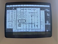
Unfortunately I'm still at the same spot. I mapped out a lot more of the machine with the scope, feel free to take a look and see if you're in the same boat overall. I'm a bit stuck though. Planning on mapping out the rest of the chips on the board to see if anything jumps out at me, but it's tedious so... not today.


croissantking

Well-known member
Time for an update on my Bolle board shenanigans.

I've built 3 of them - and they all have the same intermittent graphical problem that I can't solve. Depending on which version of the PALs I have fitted at UE6 and UE7 (either 341-0637-A + 341-0688-A, or 341-0754A + 341-0755-A) the symptoms will exhibit quite differently, which originally led me to believe one of my boards had a problem unrelated to that of the other two.

I'm really asking myself if the reloaded boards from JLCPCB I have are from a faulty batch. It's hard to conclude anything else. But how likely is this?


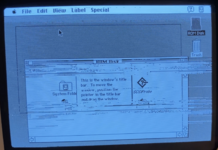
With the 06xx PALs - horizontal flashing streaks of corruption are exhibited whenever there is movement onscreen but they do not stay on-screen.

Screenshot 2023-08-03 at 02.51.12.png

With the 07xx PALs - vertical columns of corruption build up and remain on-screen.

IMG_1823.jpeg
 
Last edited:

WillJac

Well-known member
Time for an update on my Bolle board shenanigans.

I've built 3 of them - and they all have the same intermittent graphical problem that I can't solve. Depending on which version of the PALs I have fitted at UE6 and UE7 (either 341-0637-A + 341-0688-A, or 341-0754A + 341-0755-A) the symptoms will exhibit quite differently, which originally led me to believe one of my boards had a problem unrelated to that of the other two.

I'm really asking myself if the reloaded boards from JLCPCB I have are from a faulty batch. It's hard to conclude anything else. But how likely is this?


With the 06xx PALs - horizontal flashing streaks of corruption are exhibited whenever there is movement onscreen but they do not stay on-screen.

View attachment 60115

With the 07xx PALs - vertical columns of corruption build up and remain on-screen.

View attachment 60116
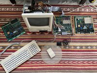
I have one doing the same thing that is on the way back to me from a customer. I made a new board for him and works fine. Truly not sure what the issue is but would be great to solve it. This one is lines and funny behaviors on screen as the mouse is moved around. All my other boards I done work fine.
 

croissantking

Well-known member
I have one doing the same thing that is on the way back to me from a customer. I made a new board for him and works fine. Truly not sure what the issue is but would be great to solve it. This one is lines and funny behaviors on screen as the mouse is moved around. All my other boards I done work fine.
Would you mind sharing a photo or video of the issue?

Did you successfully build any other boards using the same batch of PCBs?
 

croissantking

Well-known member
Here's all the work I've done. Tens and tens and possibly hundreds of hours. It'll be a hard pill to swallow if I have to move all these components to another set of boards. As I said, it's hard to believe that JLCPCB could have produced faulty boards, but I'd really like to know if this is a possibility.

If anyone has ANY ideas at all about my graphical issue, please do share. I know that both @Garrett B and @WillJac have mentioned having the same issue.

IMG_2846.JPG
 

Melkhior

Well-known member
With the 06xx PALs - horizontal flashing streaks of corruption are exhibited whenever there is movement onscreen but they do not stay on-screen.

With the 07xx PALs - vertical columns of corruption build up and remain on-screen.
For that second issue, it looks like there's 16 columns of corruption, and the corrupt part is about 1/3 of the intermediate non-corrupt-part - which would make the corruption (512/16)/4 or 8 pixels wide, basically the first 8 pixels of a 32-bits double-word. Is that over-interpreting the picture or is that correct?
 

croissantking

Well-known member
For that second issue, it looks like there's 16 columns of corruption, and the corrupt part is about 1/3 of the intermediate non-corrupt-part - which would make the corruption (512/16)/4 or 8 pixels wide, basically the first 8 pixels of a 32-bits double-word. Is that over-interpreting the picture or is that correct?
That seems to be a good analysis. @Bolle and others have suggested it’s an addressing issue which made sense at the time.

But this theory is thrown off by the other set of symptoms on the same 3 boards with a different revision of PAL chips fitted, whose symptoms have been interpreted variously as a VRAM timing issue or a power interference issue.

I think there is one trace, or one via that’s getting shorted out intermittently. It could be something non-optimal in the board design/layout that occasionally causes problems in production, but only in a small handful of cases.

Either that, or I’ve done something silly 3 times over.
 
Last edited:

Melkhior

Well-known member
That seems to be a good analysis. @Bolle and others have suggested it’s an addressing issue which made sense at the time.
While it could be a data issue, the odds off 8 data lines going bad at the same time are not high, and the odds of those being exactly 8 in the same byte even lower (though they are probably routed together, so still possible). This seem excluded by the fact that replacing the PALs changes the issue - bad data lines would stay bad. I'd suggest trying to figure out what's going on in that configuration, as it seems to have an easier failure pattern to understand.

If 8-bad-out-of-32 pixels is what the picture displays, then the odds are more than the entire byte is corrupted at once, which is either
(a) no data is written to those addresses
(b) the wrong data is written to those addresses.

The first case would probably be a defective 'write enable' signal. I can't remember how the SE/30 is built, some I'm not sure if the VRAM is 32-bits wide or 16-bits wide. 32-bits wide would suggest a single completely defective 'write enable' (stuck to low or high, more likely whichever way it disable writes). 16-bits wide would suggest some timing issue, where this 'write enable' isn't valid for the first word but has become valid for the second word. If you have a scope or logic analyzer, check those 'write enable' line to the VRAM in that configuration.

Wrong data would suggest none of the data being valid when the data write strobe hit the VRAM. If the data lines are connected directly from the CPU to the VRAM (unbuffered), then the timing for whichever mechanism enable the write in the VRAM (directly or indirectly based on /DS and /RW, presumably) is wrong - probably too early rather than too late, as data is kept valid a while by the '030. If you have a scope or logic analyzer, check the timing for the relevant signal in that configuration. If the data lines are buffered between the CPU and the VRAM, then those would be prime candidate to be double-checked.

Are those columns corrupted after looking OK, or do they never get proper data? I'm sort of assuming the second, a rather deterministic behavior.
 

Phipli

Well-known member
It might be something like you have some logic chips that are too slow and haven't settled by the time they're read?

Where did you buy your logic chips? How did you pick them?

Check your resistor and capacitor values, pull up / down values.

Have you made any component substitutions?
 
Top