I am really interested to know how you troubleshooted this successfully.
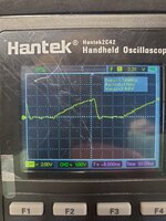
When you saw the 3MHz oscillation on the reset line, how did you know this meant something was wrong?
How did you locate the micro bridge, did you have to desolder the whole socket?
Well, So we know 2 things for sure. 1: The reset line is pulled high naturally through RP7. 2: The SONY chip, and the reset switch should be the only items able to pull the line to ground. So if I am seeing anything but a stable voltage, something is dragging the line down.
The fact that it was a steady frequency eluded me until later.
The line was only getting pulled low when the CPU was in the socket. This meant one of two things, either the CPU had a fatal flaw, or something was bridged to a line that was only actioned by the CPU.
I replaced the CPU with a known good one, so the CPU was working. I then decided to brush tone out every CPU pin to F12 which was the reset line. As i dragged up column 2 I heard a beep. Narrowed down to pin A2 which is Address 0.
Now these two pins are way to far away from each other to be bridged at the CPU socket. So we look at the schematics, and look for a chip where A0 and RESET are close to each other. UE10, Pins 40 and 41 are A0 and RESET.
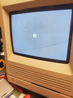
I wasn't able to visually see a bridge due to the plastic of the socket. So I fluxed and reflowed the two pins, and boom, no more short.
The fact that it was oscillating was because, and i could be wrong, the system was in a feedback loop. RESET wants to be high, and is active Low. So the CPU tries to reset its state, at boot when the sound chip pulls the reset line low, which means that A0 should be low, which causes the RESET line to ground, which causes the CPU to reset, and so on and so on.
I really enjoyed this build and a Huge thanks to Bolle for your valuable work!
.jpg")
")