• Updated 2023-07-12: Hello, Guest! Welcome back, and be sure to check out this follow-up post about our outage a week or so ago.

SE/30 horizontal circuit troubleshooting

jeauxlb

Member
Hi there, relatively new to the forums but not to the SE/30. I picked up an SE/30 today that has a known issue of a bright white line at startup. Before picking it up I had expected/hoped to look at R19 on the analogue board and swap it straight out with a new component.

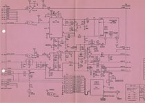
What I have found is that more than R19 is likely to be a problem. R18 and R17 and others seem to have extremely low resistances (< 10 ohms). What I would like to do is trace back the issue, but I cannot find any schematics of the analogue board — unlike the well-documented logic board. I have used the apparently similar Mac Plus schematic to get started, but am finding inconsistencies and would like to be certain.

Does anyone have expertise on diagnosing this issue, or knowledge on where to find the schematics/further details on the analogue board?
 

pfuentes69

Well-known member
I had that problem and it was not the analog but the logic board. UE8 or UF8, I don't remember... but those IC trend to go bad with cap leakage and one controls the sync
 

jeauxlb

Member
Thanks. The caps all look pretty good on the logic board so no obvious impacts to other components. I will still get to replacing them. Did you have to replace the ICs completely to get it working again?
 

pfuentes69

Well-known member
Thanks. The caps all look pretty good on the logic board so no obvious impacts to other components. I will still get to replacing them. Did you have to replace the ICs completely to get it working again?
Some people had success removing the ICs and putting them back after cleaning the cap goo under them, but these are cheap and easy to find chips, so I just replaced them.
 

Bolle

Well-known member
Do you have a horizontal or vertical line?
Only a horizontal line may be caused by the logicboard and it would mean the vertical sync signal is missing. If the horizontal sync signal was missing you wouldn’t get any screen output at all because there wouldn’t be any high voltage without a proper hsync signal.

Either way, first thing to check should be if the logicboard outputs both sync signals… 22kHz and 60Hz. If they’re present you know the fault is on the analogboard.
 

jeauxlb

Member
It's a vertical line on the screen. I don't currently have an oscilloscope to check those outputs but will chase one down to check this. Thank you for the additional background on this fault.

For now, I have seen that in-circuit resistances are extremely low for a number of resistors on the analogue board's horizontal drive components which makes me suspect the issue is there. But will confirm with the scope. Much appreciated!
 

Bolle

Well-known member
Very likely an issue with the analog board then indeed. Your Hsync is there, otherwise you wouldn't have any high voltage, Vsync obviously is there too because you've got vertical deflection. I'd expect the problem to be either mechanical (ie. cracked solder joint around the yoke connector) or in the late stage of the horizontal output.
SE Schematics.jpg
 

jeauxlb

Member
I've taken a close look and the connectors don't seem to have scorch marks anywhere on the analogue board.

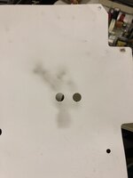
Here's a shot of the inside of the analogue board's protective sleeve. I only looked at it today — I suppose this would be suggestive of some components that have had a bit of a failure.
IMG_7669.jpg
Looking at where this corresponds to on the board, that's mainly R25, R26, and interestingly "W1" which I can't see on the schematics anywhere. This looks to be a wire with a black shroud of some kind around it. All of the other "W" elements on the board seem to be wires without shrouds, so I suppose W stands for 'wire', but am unsure about what the shroud on W1 could be (insulator perhaps?). There are some parts near the paper marks that look like diodes, as well.

I'm currently focussing on cleaning the logic board and re-capping, but afterwards will de-solder the nearby resistors, measure them, compare against markings and reconcile. I haven't looked up the parts for the diodes per the schematic but I hope they will be easily replaceable too.
 

jeauxlb

Member
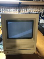
Tonight after a few solid hours of checking resistors, PSU levels, connections and the analogue board, I got it going.
IMG_7689.jpeg

What worked:
1. Checking all resistors. R26 was an open circuit so that got replaced with a 1W resistor (over-spec'd) to try and guard against any future issues causing similar failures.
2. L2 check. Unsoldering, cutting off glue, checking inductance value (approx 26.7 uH straight off the board), and giving a fresh solder job.
3. Checking PSU. -12 rail was -11.4V with a load, otherwise everything was almost spot on. Meant I could further focus on the analogue board.
4. Selecting solder points on the underside that looked fine but not in the top 50% of solders. The board really looked great, but I went over it as everything else looked fine.

I was well off the mark with my previous post; I think that was just dust from the fan. My other SE/30 (consistently working) has such a mark, too.

I'm not sure which of my small tasks was the winning factor, but I'm not going to examine it too carefully if it keeps behaving.

My thanks to all of the users of this great forum for posting their advice and experience over the years, and to the commenters in this thread.
 
Top