Early Macintosh home brew 4MB memory upgrade board development

Builder68

Well-known member
Certainly, the prototype works. This RAM chip requires 512 refresh cycles every 8 milliseconds. In contrast, the system RAM ICs on the 512K Mac necessitate 256 refresh cycles every 4 milliseconds. Clearly, there's an aspect of the refresh mechanism that I don't fully comprehend.
 

Builder68

Well-known member
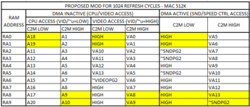
I finally figured out and fixed the sound issue with the 512 cycle refresh mod! As suspected, VA8 and HIGH being swapped between RA0 and RA8 results in some sound data being stored (initiated by the CPU) into a new location in memory, while the sound hardware for accessing memory is still expecting data at the old location. To visualize exactly how the sound hardware accesses memory, I added to the tables I previously made.
View attachment 76179
View attachment 76180
The differences are highlighted. Yellow highlight represents a known difference, and green represents an unknown. The Mac Plus table has gray text for RA9 to indicate that it isn't something the Mac 512K can be compared against.

The tables were expanded to include an additional logic input: DMA. The OE pins on the '253s are wired so they are only active when DMA is not occurring, which is anytime sound or floppy drive speed control is not accessing memory. One caveat is the '253 U13G which has its OE pin tied low, so it is always active. More on that later! The '257s OE pins are connected to active when DMA is occurring. They are the other source which creates the RA# lines, except they don't create anything for RA8 which is fully controlled by U13G.

On the Mac Plus, RA8 is created by a '253 and also as an output from BMU2. I don't know exactly what the logic in BMU2 does for RA8, but I took a guess which happened to work out.

For RA0, lifting pin 2 on U2F and tying it high, which follows the thought that swapping VA8 for HIGH when DMA is inactive means that we must also swap VA13 for HIGH when DMA is active, is correct. I suspected the missing part was that we must reintroduce VA13 for RA8 when DMA is active, specifically when C2M is high.

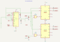
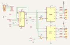
I achieved this by implementing another multiplexor. I used a '253 because it's what I have, but it could have been a '257 like the rest of the sound hardware memory access circuit. I only used half of the IC, so one OE pin was tied high to disable it. The half that I used I connected similar to the Mac's '257s for the sound hardware as follows:
Pin 1 (OEa): ~DMA - only active when sound hardware is accessing memory
Pin 2 (S1): tied LOW - never select A3 or A2
Pin 3 (A3): tied LOW - not used
Pin 4 (A2): tied LOW - not used
Pin 5 (A1): VA13 - selected when C2M is high
Pin 6 (A0): tied HIGH - selected when C2M is low
Pin 6 (ZA): RA8
Other input pins except power: tied low
Other output pin: floating

The remaining issue is that U13G is always in control of RA8, and we must make room for the new multiplexor to take control when sound hardware needs to access memory. I did that the same way the rest of the system's '253s do: by taking the OE pin for the implemented half o the IC (pin 1) and connecting it to the DMA signal.

Here's the resulting table for this logic, highlights indicate a change from the stock Mac 512K:
View attachment 76183

View attachment 76184
View attachment 76185

View attachment 76186
What you did is awesome! You figured out the missing part to reproduce the entire address multiplexing as in the Mac Plus! I think what you did with that additional 74253 is what is programmed in BMU2.

As soon as I have free time, I will implement the entire 512 refresh cycle mod on my prototype. I really don't know why it's working now using system RA0 & RA8.
 

Builder68

Well-known member
Anyway, I think that with the recent tests I made on my prototype build using modded and system RA# signals, we can be sure that the RAM IC I used will work! I'm 90% sure that the remaining issues (few bad pixels and occasional crashes) can be solved more easily once we layout a PCB based on your "512 cycles" mod. These last days have been like a quantum leap in the progress of this development, thanks to you, Golden Potato.
 

Golden Potato

Well-known member
I’m excited to read about the results of this mod on your 512 refresh cycle memory!

By the way, I tried this 512 refresh cycle mod out on my 1024 refresh cycle memory with RA9 pulled high (also tried again with it pulled low, no change), and it didn’t worked. The audio sounds okay, but the screen is mostly black with a few pixels lit up during the memory test portion. Then finally goes completely black and hangs. I’m betting a poor connection exists somewhere, but in the spirit of baby steps, I’m more interested in finding out the result on your prototype than I am with messing around with 1024 refresh cycle memory at this time.
 

Builder68

Well-known member
I’m excited to read about the results of this mod on your 512 refresh cycle memory!

By the way, I tried this 512 refresh cycle mod out on my 1024 refresh cycle memory with RA9 pulled high (also tried again with it pulled low, no change), and it didn’t worked. The audio sounds okay, but the screen is mostly black with a few pixels lit up during the memory test portion. Then finally goes completely black and hangs. I’m betting a poor connection exists somewhere, but in the spirit of baby steps, I’m more interested in finding out the result on your prototype than I am with messing around with 1024 refresh cycle memory at this time.
I cleaned up some excess solder paste and eliminated false contacts between several pins, particularly on the connections to the four 74244s. The soldered sockets on the LB are showing signs of wear from repeated removal and reinstallation of the prototype board.

Despite this, I managed to completely eliminate the pixel glitch! There are no more bad pixels under any conditions.

The Mac now boots successfully most of the time. I can even run CPU-intensive games like Dark Castle for a few minutes without crashes!.

I’m considering taking the next step and implementing the MacSnap circuit to generate CAS signals. By the way, I've realized an update: the MacSnap board connects the system RAM to be the second 512KB bank (MCAS2F, MCAS3F).

1721839563348.png

The first test will obviously be to see if the CAS generation circuit works as expected with only the 512KB system memory.

If successful, I’ll swap to the expansion memory.

If everything continues to work well, I will try using both expansion and system memory banks together.

1721839484104.png

Since I can easily remove the 47-ohm resistors from the system CAS0F, CAS1F lines (I soldered a socket in the RP3 slot), the 150-ohm resistors from the original MacSnap (MCAS2F, MCAS3F) circuit design are unnecessary.

Incidentally, it seems more likely that these are pull-down rather than pull-up resistors. The MacSnap board appears to have a third layer as a ground plane.

I am still scratching my head about the refresh cycle mechanism and the interpretation of the parameters stated in the data sheets.

My intuition tells me that I am missing something crucial to understand what is happening.

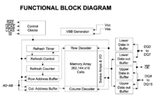
Both system and expansion memory have a 9-bit address bus. However, the 256 refresh cycles of the system memory use address combinations from A0 to A7 (see datasheet of the NEC UPD41256), so A8 is likely used for select control or parity check. On the other hand, the datasheet of the AS4C256K16FO specifies 512 refresh cycles from A0 to A8! So what's going on?

Each refresh cycle must occur at least every 15 µs, so refreshing 256 rows takes less than 4 ms, and 512 rows takes less than 8 ms.

I've included a link to relevant information. Perhaps someone could explain how the expansion memory works. I'm still inclined to believe that the crashes I'm experiencing are more related to prototype connection quality than a problem with refresh cycles.

Perhaps the UPD41256 array of 512x512 is split in two, with A8 serving as the select control between them?

The data sheet for the expansion memory clearly states that the memory is arranged in a single matrix of 512x512x16. It makes sense then that it needs to refresh 512 rows (address combinations of A0–A8). I haven't found any datasheet for a 41256 type that shows how the RAM is organized...
 
Last edited:

Builder68

Well-known member
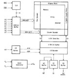
Here is a more detailed block diagram taken from the HYB 41256 data sheet (Siemens).

1721843820333.png
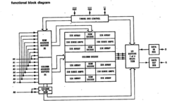
And here is a more detailed block diagram from a memory IC in the same family as the one I'm using for the memory expansion.

1721844268086.png
 
Last edited:

Builder68

Well-known member
Another block diagram from the 41256´s family (TMS4256)

1721844823226.png


Okay, the only explanation I can come up with is that the Mac's memory refresh circuitry generates 256 refresh cycles within a 4 ms interval. Somehow, when A8 (MSB) changes value, it resets the refresh counter and starts all over again. However, from the AS4C256K16FO IC's perspective, it continues refreshing the remaining block of A0-A7 addresses. Remember that there are 512 combinations for A0-A8, which is essentially repeating twice A0-A7 combinations with A8's value swapped.
 
Last edited:

Builder68

Well-known member
Meaning, this is only possible because the 9th bit (RA8) flips precisely at the appropriate time (method unknown), synchronized with the counter reset by the refresh circuitry, thereby covering the entire range.
 

Golden Potato

Well-known member
I’m excited to read about the results of this mod on your 512 refresh cycle memory!

By the way, I tried this 512 refresh cycle mod out on my 1024 refresh cycle memory with RA9 pulled high (also tried again with it pulled low, no change), and it didn’t worked. The audio sounds okay, but the screen is mostly black with a few pixels lit up during the memory test portion. Then finally goes completely black and hangs. I’m betting a poor connection exists somewhere, but in the spirit of baby steps, I’m more interested in finding out the result on your prototype than I am with messing around with 1024 refresh cycle memory at this time.
I can get a nice clear boot screen now, just by reseating some ICs in the breadboard and trying to make sure each wire is fully inserted. No noise on the screen, great clear audio on startup, but still fails with a sad Mac. Not sure if my DRAM ICs aren’t happy with only 512 cycle refresh even though RA9 is tied high, so it shouldn’t matter if those cells are refreshed. Without 512 cycle refresh DRAMs, I don’t think I’m going to be able to do much more for now. I don’t really want to move onto hacking my stuff up further to archive 1024 refresh until the 512 refresh is proven working.
 

Golden Potato

Well-known member
My understanding for the Mac’s refresh and DRAM ICs aligns with what you’ve stated. I’m probably going to sound incredibly redundant, but I’m typing this out for my own understanding!

The system counts up through the rows of memory by reading data to display on the screen. RA0-RA7 (when C2M is high) count up sequentially since the VA# signals are in order from VA0-VA7 for those RA# lines. The stock DRAM ICs use RA0-RA8 for address row/column inputs, while they only use RA0-RA7 for refresh address row inputs. I read that in the datasheet and accepted it at face value without looking further into why it can work this way. I think even modern DRAM which has LOTS of RA# signals still only use 1024 refresh cycles. Something internally going on in the DRAM to allow only one row access to refresh multiple rows.

I assumed that RA8 would not necessarily toggle every 4ms if VA8 wasn’t swapped to be tied to it, thus it was proposed to swap VA8 from RA0 (when C2M is low) to RA8 (when C2M is high). So when the video hardware accesses memory, C2M starts out high and VA0-VA8 would be latched into DRAM when RAS goes low, thus VA0-VA8 would be used as row addresses as well as be present for use as refresh addresses, then C2M would go low and the remaining VA# signals would be latched into DRAM when CAS goes low to be used as column addresses.

Each refresh cycle must occur at least every 15 µs, so refreshing 256 rows takes less than 4 ms, and 512 rows takes less than 8 ms.
This is true. You’ll notice on the datasheet for my 1024 refresh cycle DRAM that its requirements are 1024 rows in less than 16ms. It’s all the same speed counter just with an extra bit. The “counter” for us is just video accessing memory to draw the screen. The order of the VA# lines and how and when they are connected to the RA# lines is what I believe makes the difference.

Video isn’t the only thing that controls RA8 when C2M is high; if the CPU is regularly toggling A18, then it’s possible that the row would be refreshed frequently enough to maintain its data. I would chock it up to sheer coincidence, since Apple took all of these considerations into account when they designed the Mac Plus which we’ve seen the video memory addressing all swapped around to get VA0-VA8 in order with RA0-RA8 for C2M high for 512 refresh cycles.

To test the CPU A18 coincidental RA8 refresh theory, I suppose I could get my system working again by reconnecting the onboard RAM then use my oscilloscope to see if A18 is regularly toggled within 4ms only triggering when VID/~u is low, C2M is high, and ~RAS is low.
 

Golden Potato

Well-known member
Meaning, this is only possible because the 9th bit (RA8) flips precisely at the appropriate time (method unknown), synchronized with the counter reset by the refresh circuitry, thereby covering the entire range.
There’s not necessarily a precise time for this to occur other than before 4ms has passed since the last time it occurred. It doesn’t really matter if it happens out of order with respect to refresh row addresses. They don’t really care about the other rows, so long as each row gets refreshed within 4ms of the last time it was refreshed. In the case for your RAM, it’s 8ms for each row from the previous time it was refreshed. So maybe that’s what I meant instead of 4ms. I’m confusing myself… 😆
 

Builder68

Well-known member
I can get a nice clear boot screen now, just by reseating some ICs in the breadboard and trying to make sure each wire is fully inserted. No noise on the screen, great clear audio on startup, but still fails with a sad Mac. Not sure if my DRAM ICs aren’t happy with only 512 cycle refresh even though RA9 is tied high, so it shouldn’t matter if those cells are refreshed. Without 512 cycle refresh DRAMs, I don’t think I’m going to be able to do much more for now. I don’t really want to move onto hacking my stuff up further to archive 1024 refresh until the 512 refresh is proven working.
Tying RA9 high or low should do the trick.

According to the data sheet, your DRAM IC has a special function called 'Test Mode' (Page 181). At page 173, it states,'The device should be carefully initialized to prevent entry into multi-bit test mode during initialization.'

However, neither my DRAM IC nor the system DRAM ICs have such an operation mode.
 

Builder68

Well-known member
Video isn’t the only thing that controls RA8 when C2M is high; if the CPU is regularly toggling A18, then it’s possible that the row would be refreshed frequently enough to maintain its data. I would chock it up to sheer coincidence, since Apple took all of these considerations into account when they designed the Mac Plus which we’ve seen the video memory addressing all swapped around to get VA0-VA8 in order with RA0-RA8 for C2M high for 512 refresh cycles.

To test the CPU A18 coincidental RA8 refresh theory, I suppose I could get my system working again by reconnecting the onboard RAM then use my oscilloscope to see if A18 is regularly toggled within 4ms only triggering when VID/~u is low, C2M is high, and ~RAS is low.
Probably you're right. But what a heck of a coincidence if it held true. That coincidence would need to happen for both possible values of RA8, for every possible unique address combination of RA0-RA7 twice, in order for my DRAM IC to have all of its rows properly refreshed before it passes 8 ms.
 

Builder68

Well-known member
I can get a nice clear boot screen now, just by reseating some ICs in the breadboard and trying to make sure each wire is fully inserted. No noise on the screen, great clear audio on startup, but still fails with a sad Mac. Not sure if my DRAM ICs aren’t happy with only 512 cycle refresh even though RA9 is tied high, so it shouldn’t matter if those cells are refreshed. Without 512 cycle refresh DRAMs, I don’t think I’m going to be able to do much more for now. I don’t really want to move onto hacking my stuff up further to archive 1024 refresh until the 512 refresh is proven working.
During the tune-up stage of the prototype build a few days ago, I encountered the same behavior. I noticed that the Sad Mac error code was always identical. The error code pointed me to bit QD6 (Write fail). It was a connection issue with QD6 of the 74LS244 (input buffer).

By any chance, is your error code constantly repeating?

This link was very helpful.
 

Golden Potato

Well-known member
During the tune-up stage of the prototype build a few days ago, I encountered the same behavior. I noticed that the Sad Mac error code was always identical. The error code pointed me to bit QD6 (Write fail). It was a connection issue with QD6 of the 74LS244 (input buffer).

By any chance, is your error code constantly repeating?

This link was very helpful.
Thanks for the tip and the link! Definitely a loose connection on bit 12 and sometimes also bit 10. For a moment IT WAS BOOTING! But then it crashed. Since then it’s just been 031000 and 035000. I’ve wiggled, cleaned, reinserted, and everything I could think of.

It’s very motivating, and I’m tempted to build it up on a protoboard as you’ve done to help alleviate many friction-fit connections.

I also noticed my voltage was a bit low at 4.76-4.78V depending on where I measured. I bumped it up to 5.00V. Just one other little “gotcha” that can pop up when we load the system up with a bunch of additional ICs.
 

Golden Potato

Well-known member
Generate an inverse signal of RAM-R-{W} with a 7404, and AND it with ~(RAMRD) to introduce some delay to the enabling of the added input buffers (74144s) with respect to the write enable of the expansion RAM.
Any feedback is welcome!

I was looking at the Mac Plus schematic again, specifically at its bus transceivers ('LS245s). The pin used to switch the direction of the data bus to/from RAM is connected to RAMR/~WF. That's the same signal we are using to control the OE pin on the added input buffers. Interestingly, the OE pin on the '245s is controlled by a signal called ~245OE from U3E ("CAS" PAL). A simpler design could have connected the OE pin to be always active and have the transceivers switch direction based on the RAMR/~WF signal. Obviously, some important timing must be in play here. Possibly to prevent the transceivers from providing output during transitional periods to prevent brief bus contention?

I would be interested in seeing the waveforms for the Mac Plus' RAMR/~WF alongside ~245OE. I would also like to see the waveforms for the Mac 512K's RAMR/~WF, and the signal it uses to enable outputs on its '244s, ~RAMRD. Knowing the order for which these signals change and when these changes occur with respect to each other will aid us in determining what changes must be made to better align with the Mac Plus, if any.

Now if only I could get my hands on a Mac Plus logic board...
Edit: order placed; Mac Plus logic board will be on its way when the seller returns.
 

Builder68

Well-known member
Golden Potato:

I have implemented the MacSnap subcircuit for CAS Generation (version "524," without the 74259 implemented). So far, I've been trying to make it work with just the system memory, without success.

I couldn't find any misplaced or faulty connections, and I've checked all signals I traced from the MacSnap Board pictures multiple times. Everything seems correct. Any thoughts?

There is no difference whether the 150-ohm resistors are present or not. By the way, they are pull-up resistors! (I made a mistake in a previous post.)

On the MacSnap, MCAS2F & MCAS3F are used to control the system memory. The first 512 KB of expansion RAM are managed by MCAS0F & MCAS1F signals.

I haven't tried using the expansion memory yet. I assume the subcircuit should work with just the system memory. Am I missing something? Also, please note that the MacSnap board connects MCAS2F/MCAS3F signals to CAS0F/CAS1F (system CAS lines).

Here are the things I've done so far and the results:

Tried to boot with MCAS0F, MCAS1F: No sound. Same behavior as when CAS lines are open.
Tried to boot with MCAS2F, MCAS3F: No sound. Same behavior as when CAS lines are open.

The Mac boots normally taking as CAS signals the pins #15 and #1 from the 74LS139.

1722267273248.png
 

Builder68

Well-known member
Also, please note that the MacSnap board connects MCAS2F/MCAS3F signals to CAS0F/CAS1F (system CAS lines).
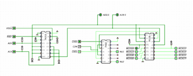
This is incorrect. I've simulated the MacSnap subcircuit and found that the system CAS signals are in sync with MCAS0F and MCAS1F signals. My apologies.

According to the simulation, it should work. There must be something wrong with my build.

1722275572085.png
 
Last edited:
Top