• Updated 2023-07-12: Hello, Guest! Welcome back, and be sure to check out this follow-up post about our outage a week or so ago.

SuperIIsiHack™ AKA SE/30's BANE . . .

Trash80toHP_Mini

NIGHT STALKER
Here's the Road Map to the early, printed & bound Mac Documentation:

xxixfigurep1.jpg.dcb8adf3a7eee6284a998b19e2398a7f.jpg


The MFHR would be the first edition of GttMFH2e as far as I know. It covers all the Compact Macs up through the Plus, IIRC. There might have been a pre-IIci/IIfx edition to cover the SE and the Mac II but it was superceded by the 2e version. Somewhere in between would have been the IIcx/SE/30 release coverage, as they were released at the same time and the SE/30 is mostly a Mac IIcx w/'030 PDS in lieu of NuBus, which wouldn't fit.


bbraun

Well-known member
I finally got my IIsi delivered today to check this out.

The 3 normal pseudo-slots for the IIsi are 9, A, and B. Pretty straightforward, and configurable card like the maccon ethernet can be configured for any of those 3 slots. The maccon ethernet can even be configured for slot E on the IIsi according to the documentation, which brings it to a total of possibly 4 usable pseudoslots.

But slots C and D are the trouble. Are these slots recognized by Slot Manager? They have no interrupt over the 030 PDS slot, but if you can get a card into those address ranges, will it be recognized?

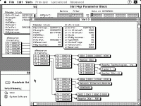
slotD.gif

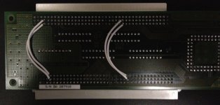
I got one of these cards, and swapped A24 and A25, which swaps both address spaces: D and E, and 9 and A. Additionally I swapped /IRQ1 and /IRQ2 (9 and A's IRQs). The swap was performed by connecting pin C27 on the IIsi side to pin B27 on the passthrough side and vice versa, then severing the traces for those two lines on the PCB. Same thing for pin C4 and B4. I threw on one of these right angle dealies to get a more vertical arrangement. There may be more involved in swapping slots 9 and A, such as swapping /IPL0 and /IPL1 maybe.

IMG_0121.JPG

I then configured the maccon ethernet for slot E and put it in the adapter, and the result is the above picture of it showing up in slot D.

So, it looks like the IIsi can have as many pseudoslots as you want, if you can:

1) Get the card showing up in the right address space.

2) Figure out interrupts.

But, the slot mgr will find it if you can deal with those two problems.

So, no more complaining about the IIsi ROM only allowing 3 pseudoslots. ;)


Trash80toHP_Mini

NIGHT STALKER
Hooray!!!! < doffs cap and throws it into the air! [:D] ]'> > GREAT job herr braun! :approve:

If we're going to be adding additional cards to the IIsi and SE/30, it might behoove us to populate those SIP Zener pads and run the patchwires through/from them and cut the affected traces above the Zeners. Dunno if it's necessary, but dumping signal over-voltages to ground for protection over an extended bus or cable is always a good thing, IIRC!

_________________________________________________________________________________

On the Rocket friendly PSU upgrade front:

I just doodled out the basic PCB requirements for my stealth 250W ITX PSU upgrade at work today. Gotta fire up the vinyl cutting plotter for making my first new PCB masks in a decade. CrapShack/PhoneHut is getting back to its RadioShack Roots just in time . . .

. . . they've got DS Copper Clad FRP & Etchant in stock again! 8-o

I've got what I need for converting the non-switching ITX PSU to a switching IIsi PSU in hand already. I can harvest the AC I/0 headers for installation on the adapter board, the Wiring Harness/Mobo Connector and possibly the two fuse holder clips off the DOA IIsi PSU's PCB. The power connector and wires can be desoldered from the ITX PSU's AC socket and then soldered to the fused output pads of the Adapter PCB. Then that can be plugged right onto the ITX PSU's input headers.

I'm going to go ahead and make a few simple home-etched boards for the project, with a prototyping area included for any Soft Power Shenanigans that might become necessary. I'll make sure the PCB is compatible with the Q700 Stand-In PSU I have on hand as well.

Things are beginning to move along nicely, buddy! :cool:

Edit: Will the I/O hacked SuperMac "Wrong Angle" adapter card fit into your SE/30's PDS w/o frame modification? Will the RCPII/IIsi Card fit on top of the Hacked Adapter nicely within the confines of the SE/30?


bbraun

Well-known member
The SuperMac card looks like it'll fit in the SE/30 fine, but the RCPII/IIsi looks like it'd be "challenging".

I've already been using the wrong angle stuff in my SE/30 with the maccon ethernet and a Radius TPD card, but with each level, it indents one card's width further towards the CRT, so the stackable limit is pretty much however many you can stack before hitting the CRT I guess.


Trash80toHP_Mini

NIGHT STALKER
That's what I figured, same story for "stacking" them across the bottom of the IIsi MoBo. I've finally got some solder paste and low temp solder (QuickChip type) on the way. I'll be adding machine pins to the "solder cones" of the IIsi MoBo's PDS when it gets here. [}:)] ]'>

Then I'll noodle out how best to "Flop Over" Adapt the PDS Slot connector on one of my boards so that they'll all be as high as the passthru connector shrouds will allow.


bbraun

Well-known member
I've been reading more about the 030 PDS in Designing Cards and Drivers, and it seems like for the SE/30, VIA2 has the pins available for IRQ's to be routed for slots C & D. But since the IIsi doesn't have a VIA2, and it is replaced by the Ram Based Video of the IIci, partially emulating the second VIA's registers, I'm not sure the pins even exist to be able to route IRQs for those slots. I'll leave that to you hardware guys.

I'm also wondering what the Function Code pins (FC0-FC2) do. The best description I can find is: "Three bit function code used to identify the address space of the current bus cycle". I'm wondering if the function code should be adjusted when swapping slots around like I was doing with the SuperMac card.


Trash80toHP_Mini

NIGHT STALKER
I'd like to be able to snag the interrupt for the on-board vampire video. The IIsi disables the Memory buffering for it if there's no sense pin signals on the the DA-19. As I'll be removing that connector from the MoBo or cutting its traces and patching a subterranean RCPII/IIsi cable to it the SuperIIsi™ will never have a use for the internal video interrupt.


bbraun

Well-known member
That won't really help AFAICT. You can get the interrupt, since all slots are ORed into /SLOTIRQ. The point of the VIA2 register is to decode which slot had the interrupt. If your card interrupts and you send it to the RBV video interrupt, that's telling the processor the RBV video interrupted, which isn't what you want. What you need is for the corresponding bit in the emulated VIA2's register A (I think this is RBV register C?) to indicate your desired slot had an interrupt. /IRQ0-3 from the 030 PDS correspond to slots 9, A, B, and E, which correspond to bits 0, 1, 2, and 5 of the second VIA's register A. So you somehow need to get bits 3 and 4 of that register to correspond to slot C and D /IRQ lines. What I'm saying is in the SE/30 these correspond to physical (and available) pins on VIA2, AFAICT. On the IIsi, I'm not sure these pins exist. Without the appropriate bit being set in that register, you don't get proper interrupt routing in software. It is possible to either modify SlotMgr or some other hack to alter the routing to do what you want, but that has changed from a pure hardware mod into needing drivers and/or possibly a ROM modification.


Trash80toHP_Mini

NIGHT STALKER
Which brings me right back to the PAL on the Megabuck$ Japanese Three Slot SE/30 Adapter.

Does anyone know if that's a pure hardware hack or if there's an init/driver necessary for it to work? :?:

My second thought would be that VIA2's function on the IIsi may be handled, in part, by the NuBus Bridge Chipset. If the NewBus Bridge tells the Mac that there's a DeclROM on a NuBus Card in slot X, then it's using interrupt Y by definition, therefore the Slot Manager ought to handle it as such without the need for inits/drivers.

It may be a stretch, but the NuBus Signal and the NuBus Chipset availability seem to be the defining characteristics that differentiate the two machines and their near-identical '030 PDS implementations.


Trash80toHP_Mini

NIGHT STALKER
We may be looking at this particular case backwards now that I think of it. We're NOT talking about the IIsi as the CPU in the SuperIIsi™ whatsoever.

The Radous Rocket is the CPU and will only need the Addresses and Interrupts available on the PDS to talk to Cards at those address/interrupt locations on the IIsi's I/O Bus.

The Rocket will have taken over the NuBus, becoming the Master and enslaving any Card it can address through the NuBus Chipset . . . and possibly beyond. }:)

I'll have to chop up one of my extra Gemini Cards for the machine pin hack, so that I can plug straight into the IIsi NuBus Adapter's Slot to test this out. Both Duo NuBus Slot IDs are different than the IIsi's Slot ID and the PDS IDs available, IIRC.

Hrmmmm . . . :?:


bbraun

Well-known member
How does the Nubus bridge tell the Mac there's a declrom somewhere? That goes against my understanding of how this all works, so if you've got something specific in mind, I'm all about increasing my understanding...

Here's my understanding of the process from connector to System software:

The /NMRQ pin of the Nubus connector on the Nubus bridge adapter goes to /IRQ1 of the 030 PDS connector, and the ID0-3 pins of the Nubus connector indicate to the card to use slot 9. In the IIx, each slot's /NMRQ line goes to VIA2 register A bits 0-5 (one per, slot 9's /NMRQ goes to bit 0, slot A goes to bit 1, etc.). Bits 0-5 of VIA2's register A are then ORed by VIA2 (or RBV, in the IIsi/IIci case) into /SLOTIRQ, which is the actual processor interrupt. The bridge adapter only supports 1 card at slot 9, so /NMRQ goes to /IRQ1. When /SLOTIRQ indicates an interrupt, the CPU interrupts, the SlotMgr's interrupt handler fires, the SlotMgr then checks VIA2 register A to see which (one or more) slots interrupted, and fires off the appropriate interrupt handlers.

So... A (pseudo)slot can interrupt the CPU by toggling /SLOTIRQ, but unless the appropriate bit gets set in that VIA2 register, no one knows what interrupted, and that slot's interrupt handler (if any) won't get run. There's no way an 030 PDS card can inform SlotMgr to go look at some other bit to determine which slot interrupted.

Now, this is all pretty machine specific, since AFAIK, later models have a different way of checking which slot interrupted. As it stands, the IIsi/IIci are already kind of different from the II/IIx/SE/30 since the RBV emulates this VIA2 register and the II/IIx/SE/30 have an actual 2nd VIA.

This gets me thinking whether the Nubus bridge could support additional Nubus cards if ID0-3 were set appropriately, and the additional slots' /NMRQ line went to the corresponding /IRQ line of the 030 PDS.

But again, that's just my understanding, so if there's something specific I should be looking at, let me know...

As for the Rocket, I don't think anything changes. The above is how the system works, and the Rocket has to work within the confines of the existing system. A master in Nubus terminology simply means whoever is initiating the addressing at the current time. Multiple cards can be masters on Nubus, just not during the same cycle. The CPU is always capable of acting as a master, as are Rockets, some SCSI cards, etc.


Trash80toHP_Mini

NIGHT STALKER
As I understand it, when the Rocket re-boots in Accelerator mode after enslaving the host CPU as a mere I/O CoPro, it runs the NuBus via AppleTalk over NuBus and does Block Transfer Mode with all Compatible Cards.

As I understood it back in the day, the Rocket acted independently of the host CPU, interpreting and issuing the interrupts for the NuBus Slots over the NuBus.

In this way, the Saturn V used a "lowly" SE/30 to copy its ROM to a multitude of Rockets set up in a huge expansion chassis without any regard for the SE/30 as anything but a simple controller terminal . . .

. . . amd the SE/30's not even NuBus Compatible other than via the Two Slot ExPanse Chassis, AFAIK! }:)


bbraun

Well-known member
Looking at how things are routed, I just don't see a way a Nubus card can get any interrupts except its own without the host CPU and and consulting VIA2/RBV. Particularly when the Nubus card is sitting off a Nubus bridge off an 030 PDS. The signals just aren't present.

The Rocket can read VIA2/RBV directly, since it is capable of operating as a Nubus master, but it can't get /SLOTIRQ (or onboard SCSI interrupts, Sound interrupts, Egret-based NMI, etc.) without the host CPU. Once the Rocket has software running on the host CPU, nearly anything is possible, but it still has to work within the constraints of the hardware of the system it is running in while (mostly) preserving software compatibility.

The Rocket does change one thing pretty substantially though: it does complicate any software/ROM-based solutions to this problem since any software would need to be compatible with whatever contortions the Rocket software is doing.

But anyway, that's just my understanding, which is definitely subject to reality checks! :)


Trash80toHP_Mini

NIGHT STALKER
I was thinking that since it is the Rocket running the Slot Manager in Acceleration Mode, not the CPU relegated to hosting the non-NuBus I/O, similar to the 6502(?) I/O co-processors on the IIfx MoBo, the Rocket may be able to pull at least a few rabbits out of its hat.

I'll need to crack the books and DevNotes for info on Interrupt Lines/Slot IDs/PseudoSlot assignments for multi-slot implementations in oter Macs of the IIsi Adapter's NuBus ChipSet. IIRC, it's the same chipset found on the DuoDock (Rev 1) and possibly the IIci, IIcx and earlier II series Macs.

A few patch wires between a NuBus Slot Section hacked from another machine and the NuBus Adapter Bridge ASICs might do wonders for a Rocket running rampant over a brain-dead IIsi! }:)


bbraun

Well-known member
Using JDW's pictures of the SE/30 twinspark thing, these are my best guesses at pin assignments of that chip on the adapter:

1 - CPU A37 (+5V)

2 - CPU A7 (/STERM)

3 - PDS A10 (/BGACK) & Cache B29 (A20)

4 - NC

5 - NC

6 - NC

7 - NC

8 - NC

9 - NC

10 - NC

11 - NC

12 - CPU A10 (/BGACK)

13 - JP3

14 - NC

15 - NC

16 - Cache C38 (CPUCLK)

17 - PDS C38 (CPUCLK)

18 - Cache A2 (/PDS.MASTER)

19 - NC

20 - NC

There might be connections I can't see, or I might have gotten all the assignments backwards. I followed the numbering on the board, and I don't know if that's accurate. But, it seems to be doing something more complex than just mucking with slotid.


Trash80toHP_Mini

NIGHT STALKER
I'm confused now . . . :?:

After looking at those pics:

It looks like the ArtMix card simply converts the SE/30 PDS to a IIci PDS for using the accelerator . . .

. . . so isn't that PAL doing the same function as the PAL on the "official" SE/30 Adapter card and only providing a PassThru for a single SE/30 68030 PDS Card?

Is there even room to stack TWO Cards on top of that thing? :?:

Now I seriously doubt that the PAL on that card has anything at all to do with the PassThru connector or addressing an additional PDS slot . . .

. . . probably just another ASSuME or memory leak brain boo-boo! :-/


Trash80toHP_Mini

NIGHT STALKER
I just re-read this thread to refresh the gray matter memory, spell-check, grammar check and clarity check my .TXT output and now my brain really hurts!

The extra batch of Machine Pin Strips have been here for over a week and the solder paste just might arrive today!

I've had the IIsi MoBo and bits transferred to the cherry IIsi case I got on eBay a few months back for a couple of days.

So this morning it's time to chop holes in the bottom of the yellowed original case to lower the floor of the basement for the PDS Cards. }:)


bbraun

Well-known member
Ah, yup, a IIci cache connector makes sense! That connection to the cache card's BB29 pin becomes /BGACK, and makes a lot more sense.


Trash80toHP_Mini

NIGHT STALKER
Excellent! The building blocks are stable in the 'ole noggin' once more! :approve:

If you can noodle out ( "clean room" reverse-engineer ) the function of the PAL on the "official" SE/30 adapter card, we can design/fab a production run of lower profile "ArtMix/twinspark/whatever "type" adapter cards that can possibly provide correction for at least one "PDS Drift Unit" for the "Wrong Angle" PDS Card StackHack! [:D] ]'>

:cool: -ness! [;)] ]'>

edit: Maybe techknight can figure out how to do it with an embedded proc that will also multiplex/convert the PDS address/interrupt gobbledegook to do a three PDS Card Hack . . .

. . . unless a NuBusChipSetGraftHack™ for a vertical internal 7" NuBus Card Slot makes sense . . . }:)

edit: Move the NuBus slot as far forward as possible so a plate-less LittleRedRadiusPixelRocket™ faces the rear of the SE/30 and an internal cable can do a VGA conversion on the way to an HD-15 connector on the EtherNet breakout panel! Choose the original NuBus Chipset and it' becomes available for rework/forwardwork from a lot more donors than the relatively scarce IIsi NuBus Adapter. [}:)] ]'>


Trash80toHP_Mini

NIGHT STALKER
Let's try this again: YO! bbraun, come on back for some playtime!

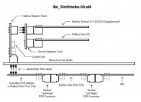
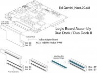
I've Updated the TWO SLOT IIsi Nubus Card hack . . . thread with a couple of diagrams, one of which definitely belongs here . . .

I played around with the NuBus Adapter Diagram from the DevNote and wound up doing a major overhaul.
This diagram shows both the NuBus and Basement PDS hacks, both done by soldering Machine Pin strips to the soldertails of the Gemini Card and the IIsi PDS respectively. One of the two cards mentioned will have its Right Angle PDS Male Connector removed and replaced by Machine Pin Strips in their standard configuration as high reliability sockets on a PCB.
IIsi_SlotHacks.00.jpg

Lets see if this clears anything up! ::)

This diagram basically shows the Gemini Card's origins and how it needs to be modified for the TWO SLOT hack.

IIsi_Gemini_Hack.01.jpg

 
Top