• Updated 2023-07-12: Hello, Guest! Welcome back, and be sure to check out this follow-up post about our outage a week or so ago.

restoring a battery-bombed IIcx

bigmessowires

Well-known member
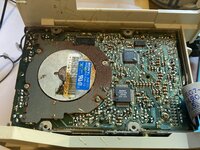
Inspired by @jmacz's thread battery bombed IIci, here is my battery bombed IIcx. I mostly wanted the video card that came inside this machine (for testing purposes), and the dead IIcx was just a bonus for a few dollars more. I've never tried to restore a significantly-damaged machine before, so this will be interesting.

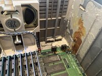
The GE power supply looks visibly OK but I haven't yet tried it. The floppy drive has sticky drippings like honey all over the bottom.

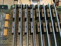
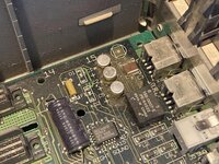
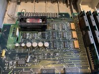
The logic board is obviously damaged, but isn't the worst. There's battery leakage (I think) along the front of the logic board near the battery holder, under the RAM, and near the reset/interrupt switches. Also maybe some cap leakage damage in other areas of the logic board. The case itself also has areas of corrosion or rusting.
IMG_3839.jpg

IMG_3837.jpg

IMG_3838.jpg

IMG_3836.jpg

IMG_3840.jpg

Um... are D1 and D2 supposed to be missing there?

What would be your step 1 here for neutralizing all the evil goo, before I try fixing anything? Would you submerse the whole board in something, hose off the case with a garden hose? I have lots of 99 percent isopropyl alcohol and some old tooth brushes for scrubbing, but anything else for cleaning I'll need to go get.
 

Phipli

Well-known member
Um... are D1 and D2 supposed to be missing there?
I believe so.

If I remember, they're fitted in some machines and not other. Seems there were two configs over time, or possibly depending on which source was used for dual sourced parts.

Similar situation with LC 475s. There were multiple RAMDACs used and some needed a support chip, others had it integrated.
 

bigmessowires

Well-known member
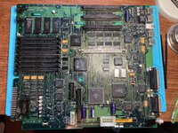
The floppy drive still looks like a rust bucket, but the IIcx logic board cleaned up pretty nicely! I used lots of alcohol, swabs, a toothbrush, and a metal scraper. The worst part is near the battery, and the battery holder will need to be replaced (part number?), but the logic board traces might actually be OK. I'll let it dry for a while more, then replace the RAM and try powering it up.

IMG_3842.jpg
 

dougg3

Well-known member
Nice! I believe the part numbers you’re looking for are Keystone 108 for the holder and 108C for the cover. Digi-Key has plenty of them.
 

bigmessowires

Well-known member
Thanks for the part number. I thought maybe I'd get lucky here, and I'd power on the computer to find that it just works, but it won't turn on at all. Using a known-good power supply (ATX with my adapter), nothing happens when I press the power button or keyboard power switch. I could look into debugging the startup circuit, but maybe I should recap the board first?
 

Phipli

Well-known member
Thanks for the part number. I thought maybe I'd get lucky here, and I'd power on the computer to find that it just works, but it won't turn on at all. Using a known-good power supply (ATX with my adapter), nothing happens when I press the power button or keyboard power switch. I could look into debugging the startup circuit, but maybe I should recap the board first?
The startup circuit has critical chips around the battery and the row of caps next to it. It's often haken some damage. Check for vias and broken traces, as well as chips needing cleaning or replacing.

But also, yes, recap it to remove that variable, but note macs often run without caps.
 

joshc

Well-known member
Um... are D1 and D2 supposed to be missing there?
Yes, normal. Though I can't say why but I've had... lost count now, maybe 4 or 5 IIcx over the past few years and I think most were missing D1 and D2.

You should expect to have to replace these logic ICs too. Try it after a recap anyway but these are all part of the startup circuit and get badly affected by cap goo.

1697774915398.png

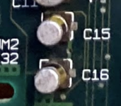
Another thing to bear in mind... the polarity of caps C15 and C16.

1697775070806.png

See https://recapamac.com.au/macintosh-iicx/

which mentions:

The screen printing on the logic board indicates that these caps should have positive to the right, but the original caps have positive to the left. The original placement of the caps is correct (as is the guide below).

Interesting hand writing here... where did this machine come from?

1697775022761.png
 

bigmessowires

Well-known member
Ah yes, after checking that startup area closely, the chips and traces look OK but I think some of the vias are rotten. I'll trace it out tomorrow.

Yes I also noticed that writing scratched on the edge. Schools would often write on the computer cases, but the logic board? Looks like WDL DORMAR L4(5)81 DL(6)? The computer came from an eBay reseller so I don't know the past history.

Is there anything I need to neutralize the cap goo so it doesn't do further damage, other than washing it away with IPA and swabs?
 

joshc

Well-known member
Is there anything I need to neutralize the cap goo so it doesn't do further damage, other than washing it away with IPA and swabs?
Fancy people have ultrasonic cleaners and use those to really get rid of everything that shouldn't be there, cap goo and otherwise. I am not that fancy, good ultrasonic cleaners are quite pricey and very large.

So for the mere mortals of us... A proper scrub with hot soapy water, just like you'd clean your dishes with, is fine. And then rinse all that off with water and then with isopropyl alcohol and leave to thoroughly dry (or if impatient, attack it with hot air but it will still take time to get it all completely dry).

they are recommending replacement tantalums with the same voltage rating as the original electrolytics? I thought the wisdom was to derate by 50 percent?
I have never derated caps when replacing with tantalums - but that was before a few people voiced their opinions rather loudly on that subject, a few years ago. So yes, I believe generally speaking that is the 'correct' thing to do. However, I have yet to see a problem myself from using 16V tantalums where 16V electrolytics were used. There is a very well known capacitor in the IIfx (C3?) ...its the one near the internal SCSI hard drive connector - that one is known to blow if not derated.
 

jmacz

Well-known member
I have been using the same voltage tantalums except the one @joshc mentioned on the IIfx .. as he mentioned due to issues with blowing.

For cleaning, I don’t have a large enough ultrasonic cleaner so I usually use dish soap and water, followed by complete submersion in isopropyl alcohol for 30 minutes and then air drying for a few hours.

Looks like fun! Good luck!

Oh, per your other thread on recapping, I was religiously using hot air to remove SMD caps, until @joshc mentioned having never lifted a pad using the twist method so I gave that a try and although nerve wracking, it’s fast and works. Been using that method for the last hundred or so caps I have replaced and haven’t lifted a pad yet (knock on wood) and it’s just so much faster.
 

Phipli

Well-known member
I have never derated caps when replacing with tantalums - but that was before a few people voiced their opinions rather loudly on that subject, a few years ago. So yes, I believe generally speaking that is the 'correct' thing to do. However, I have yet to see a problem myself from using 16V tantalums where 16V electrolytics were used.
Despite the rather... verbose original commenter, it is the right thing to do. It reduces the chance of firey surprises and causes no downsides, so you might as well. They're a small amount more costly.

I beep out what is on the 12V and 5V rails and use 16V parts on things that I know only see 5V to get rid of my stock of 16v parts.

Remember this is probabilities. None of us are likely to see an issue where one fails, but I really don't want to see it happen - and we know it does (people have turned up here with 650s with burnt out tants, and I have seen exploded tants in other things I've repaired).

It's part of ensuring recap and forget.
 

max1zzz

Well-known member
There are also other cap options if your worried about derateing, Polymers have become a popular choice as they are solid so won't ever leak but look much like the original electrolytics, Ceramics are also another option that (as far as I know) don't need derateing.

There is also the option of just fitting new electrolytics but then there is always the chance of the leaking in the future (I chose this option for may of my macs thinking "well if I have to recap again in 20 years that's OK" but I was thinking that more than 10 years ago now! it'll only be a handful of years till i need to start re-recapping stuff...)
 

bigmessowires

Well-known member
I have the same thoughts about re-recapping. Surely nobody will still be using these computers in another 20 years?!?

Well for this IIcx I have purchased 16v tantalums, largely because I was able to find links to specific part numbers to order and didn't want to spend time searching thousands of options for higher-voltage capacitors with the appropriate sizes and specs.
 

bigmessowires

Well-known member
followed by complete submersion in isopropyl alcohol for 30 minutes

How much alcohol does that require? (Consults slide rule...) I think it would need more than a whole 16 ounce bottle to fill a tub to a depth of a few mm for submersion.
 

bigmessowires

Well-known member
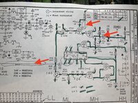
I've beeped out the power-up circuit, and found three bad connections. PFW is interesting: the trace follows a meandering path around the PCB and I can't find exactly where it's broken. Just to be double-extra-sure: this goes to the power supply connector pin 9, right? In theory I could connect that pin to +5V and the Mac should turn on regardless of the power-up circuit?

IMG_3843.jpg

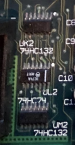
Anybody know where the rest of UM2 is on the schematic? Only two of the four NAND gates are used on this page, and it doesn't seem to appear on any other pages.
 

bigmessowires

Well-known member
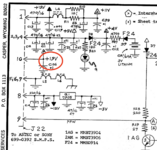
Also why does the schematic show that pin 10 of the power supply is 19V? I thought that pin was the 5V trickle supply. Surely there isn't any 19V supply.

Untitled 3.png
 
Last edited:

dougg3

Well-known member
Ahh, that's weird about Bomarc's schematic calling it +19V! This won't solve the UM2 mystery, but Gamba had another startup circuit schematic diagram for the IIcx that you might find useful:


On Gamba's schematic, pin 10 is correctly listed as the +5V trickle supply. And yeah, Gamba's shows the trace between R28 and R29 going directly to pin 9.

This is very similar to the II/IIx power supply circuit I examined in detail on my blog. I'm pretty sure you should be able to momentarily short pin 9 to the trickle +5V on pin 10 to jump start the power supply. Afterward, the power supply (through D7 and R28) should keep it high, and thus it should stay powered on.
 
Top