• Updated 2023-07-12: Hello, Guest! Welcome back, and be sure to check out this follow-up post about our outage a week or so ago.

restoring a battery-bombed IIcx

jmacz

Well-known member
How much alcohol does that require? (Consults slide rule...) I think it would need more than a whole 16 ounce bottle to fill a tub to a depth of a few mm for submersion.

A lot :)

I try to recycle the alcohol as much as I can. Got used to recycling for 3d resin printing. I keep my general cleaning alcohol and 3d resin cleaning alcohol separate. But I use various filters to repurify the alcohol (as much as possible) and then store it in a glass air tight jar. I use it a few times before letting it evaporate outside (open jar).
 

bigmessowires

Well-known member
After patching the broken traces that I'd found, unfortunately the IIcx still won't power on. If I bridge pins 9 and 10 on the PSU then it turns on but there are no other signs of life, and it turns off again as soon as I remove the bridge wire. Need to keep debugging.

Would old/dead capacitors conceivably prevent the computer from starting up? I still need to recap this thing. Depending on the failure mode of the capacitors it seems possible.
 
Last edited:

cgp

Active member
Anybody know where the rest of UM2 is on the schematic? Only two of the four NAND gates are used on this page, and it doesn't seem to appear on any other pages.

They are unused gates. It's similar for the IIci too. The startup logic was misfiring on one of my IIci's and I considered substituting an unused gate (turned out to be a near short elsewhere).

Note the caps in this circuit need to be good for the power-on/-off to work; they're used as RC timers. I had a IIcx that would power-on OK but refused to power-off .. this was due to 2 replacement caps (C15/C16) being installed with the wrong polarity by the previous owner.
 

bigmessowires

Well-known member
Yeah C15 and C16 are labeled backwards on the silk screen! So this IIcx actually *is* turning on with the power switch, but then immediately turning off again. If I hold the power switch then the power LED blinks rapidly. Probing around the startup circuit, I think the turn-on part of the circuit (top of Gamba's diagram) is working, and the stay-on diode D7 is also working, but the turn-off part of the circuit (bottom of Gamba's diagram) is triggering when it shouldn't.
 

Phipli

Well-known member
Yeah C15 and C16 are labeled backwards on the silk screen! So this IIcx actually *is* turning on with the power switch, but then immediately turning off again. If I hold the power switch then the power LED blinks rapidly. Probing around the startup circuit, I think the turn-on part of the circuit (top of Gamba's diagram) is working, and the stay-on diode D7 is also working, but the turn-off part of the circuit (bottom of Gamba's diagram) is triggering when it shouldn't.
That can happen when there is a short?
 

cgp

Active member
Yeah C15 and C16 are labeled backwards on the silk screen!
I think the issue is that they're not explicitly labeled but they're the reverse of their neighbors that are. So it's confusing.

If you're installing tantalums, at least putting these in backwards won't cause fireworks! Unlike the LCIII's infamously mis-labeled C22.
 

bigmessowires

Well-known member
I don't think there's a power-ground short, but I'll check. When I was testing it, I'm pretty sure I saw the base of Q3 go high, which turns on the transistor and actively shuts down the computer by forcing PFW low. Another possibility is that D7 is simply broken - this is the diode that keeps the computer on after the initial turn-on.

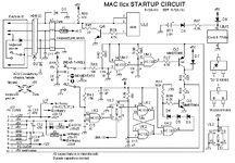
macIIcxsch.GIF

Fortunately the power-up circuit is well-documented, thanks to the work of others, and it should be possible to diagnose by probing around different points in the circuit while attempting to turn on the computer.
 

bigmessowires

Well-known member
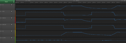
I connected probes to the 5V supply as well as PFW, the sides of R28 and R29 that are opposite PFW, the input to D6, and the output of the flip-flop at UL2 pin 5. When I try to turn on the computer, there's a repeating pattern. Here's the first cycle and start of the second.

iicx-startup.png

At first Q2 is on, and PFW goes high as expected. R28 and R29 also go high. Since Q3 is off, there is no current through R29 and the voltage on the other side of the resistor basically follows PFW.

Even while PFW is high, nothing happens for about 75 ms until the 5V supply voltage finally begins to climb. I'm not sure why the long delay here... maybe this is how long it takes my PSU to kick on? I'm using an ATX PSU with my 10-pin adapter, which works fine in my IIci.

Notice the input to D6 climbs in lockstep with 5V. This is not correct and not expected here. This is the "turn off" signal from UK2 pin 6, and when the voltage gets above 4 diode drops (about 2.4V) then Q3 will begin to turn on, pulling PFW low and forcing a shutdown. After about 6ms that's exactly what happens.

PFW is low for about 40ms before the 5V supply voltage finally begins to decrease. Once again, it seems like the PSU is very slow to respond?

The flip-flop output at UL2 pin 5 is low the entire time, which is also incorrect. That's the /RESET input to the SR latch. It should be high thanks to the preset at pin 4 connected to C10, which will be low when the circuit is first powered on. But even if /RESET is low, /SET should also be low - it's the voltage from capacitor C10 which will take a while to charge up. With an RS latch, if both /RESET and /SET are simultaneously asserted then the output will be 1, which should make the output at UK2 pin 6 be 0, which should not activate Q3's shutoff behavior.

So I'm thinking either C10 is bad, or something else if forcing the flip-flop output low, and either way the shutoff behavior gets triggered. I think I need to probe more points in the shutoff section of the circuit to learn more.

Or maybe this isn't worth debugging any further until it's been recapped? Still waiting on capacitor delivery...
 
Last edited:

dougg3

Well-known member
Hmm...what about UL2 pin 1? Have you confirmed that it's not low? That's the signal coming from UH6 (VIA2) pin 13 to shut off the computer from software. Could that be bad and messing with the flip-flop's operation?
 

Phipli

Well-known member
PFW is low for about 40ms before the 5V supply voltage finally begins to decrease. Once again, it seems like the PSU is very slow to respond?
This is due to the capacitors - powersupplies tend to stay on, sometimes quite a long time.

Even while PFW is high, nothing happens for about 75 ms until the 5V supply voltage finally begins to climb. I'm not sure why the long delay here... maybe this is how long it takes my PSU to kick on? I'm using an ATX PSU with my 10-pin adapter, which works fine in my IIci.
75ms seems pretty fast, it's a big analogue circuit with output capacitors to charge, even if the primary side is charged.
Notice the input to D6 climbs in lockstep with 5V. This is not correct and not expected here. This is the "turn off" signal from UK2 pin 6, and when the voltage gets above 4 diode drops (about 2.4V) then Q3 will begin to turn on, pulling PFW low and forcing a shutdown. After about 6ms that's exactly what happens.
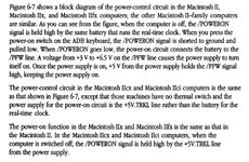
Is the trickle voltage from the PSU latching _PFW high like it is meant to? If it wasn't, the 5V would collapse as soon as you took your finger off the button.
1000013510.jpg
I guess not because it is cycling. It would just happen once.

This does sound like what happens when there is a short though. Mac PSUs go "tickticktickticktick" and turn off as soon as you let go when there is a short.
 

bigmessowires

Well-known member
OK I'll assume the laggy PSU response time is normal.

D7 latches PFW high once it's on. If that were broken, we should see the absence of an "on" signal at R28, instead we're seeing the presence of an "off" signal at R29 and D6.

I don't think it could be a short, since the 5V supply does reach a full 5V and stay there for about 30 ms. I also measured the +5V to GND resistance directly and it's about 15 ohms, which seems plausible. Unfortunately this may be all the time I have to investigate it today, so the mystery will need to wait.
 

cgp

Active member
It perhaps goes without saying, but the IIci startup circuit is identical (modulo labeling) .. so you can compare the IIcx with that. And you can of course swap PSUs between them.
 

bigmessowires

Well-known member
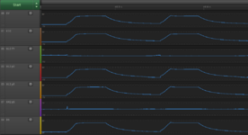
I got some more data on this IIcx. I'm troubleshooting this highlighted part of the circuit, and measuring voltages at the seven points marked in red. D6 is the "turn off" signal that will enable transistor Q3 to actively turn off the computer.
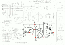
macIIcxsch-2.GIF

Here's what I'm seeing when I press and hold the power switch:
iicx-startup.png

A lot of this doesn't make sense to me. C10 rises at 5V rises, as it should, but it's always about 0.9V lower than the 5V supply even once it plateaus. It should be the same voltage. I can't explain that.

UL2 pin 1 is the active low shutdown signal from the VIA chip, connected to the asynchronous clear input of the flip-flop. It's low the whole time, meaning the VIA is trying to shut off the computer. This is wrong.

UL2 pin 3 is the clock input to the flip-flop, its job is to shut down the computer if you press, release, and press the power button a second time. The way it's wired it's basically an inverter for the voltage on C15. When the power button is held in, then C15 is grounded, so the inverter output should be high and UL2 pin 3 should be as high as the power supply can make it. This looks like it's working correctly.

UL2 pin 5 is the output of the flip-flop. In a normally working computer, this should be high (as high as the power supply can make it) until you choose to shut down from the Finder menu. But in this case because the VIA is unexpectedly driving the asynchronous clear low, the flip-flop output should be low. So this is "right", but because it has wrong inputs, it ought to be wrong.

UK2 pin 5 is the output of the RS latch (the cross-coupled NAND gates). The latch's set input is active low and is at UK2 pin 1, the voltage on C10. The latch's reset input is active low and is at UK2 pin 9, the output of the flip-flop. In a normally working computer, C10 holds the set input low for a moment during startup to force the latch value to 1. The reset input remains 1 until the flip-flop is triggered. When the latch's output is 1, then the NAND output feeding D6 will be 0, transistor Q3 won't be enabled, and the shutdown behavior won't be activated. So for correct operation here UK2 pin 5 should be high (as high as the 5V supply can make it).

But that's not what happens. Aside from a little glitch on the first cycle, UK2 pin 5 remains low the whole time.

There's something about this whole circuit that I don't understand. All these 10 and 47 uF capacitors are there to provide some predictable initial voltages for the startup circuit - particularly C10 which sets the RS latch and asserts the flip-flop's asynchronous preset for a few moments after power-up. But to do this job, C10 must charge up more slowly than the 5V supply rail itself, with its big 470 uF capacitor. I believe this is the reason for the existence of R26: it slows the rate of charging on C10. Somehow that's not happening though, and C10 charges up almost as quickly as the 5V rail itself. That means the initial set and preset signals are deactivated before the 5V supply has even reached its full voltage. Something definitely seems wrong there, either the 5V supply is rising slower than expected or C10 is rising faster than expected.

Hmm... the time constant for the RC circuit composed of C10 and R26 should be R times C, 47 uF * 15K ohms = 0.705 seconds for the capacitor to reach 63.2% of its final value. But it seems to be rising from 0 to its final value in about 10-20 ms. So maybe C10 is bad?

TLDNR - This method of analysis was less useful than I'd hoped. It maybe points towards a problem with C10, possibly also a problem with the VIA, but I'm still looking at "recap the board and then try again", which is where I started. :)
 

joshc

Well-known member
Because I'm a lazy so and so and also don't have a scope, I've never done that sort of diagnosis when repairing any startup circuit. It's definitely useful if you've exhausted the easy options like recapping, but I would always start with that. Also, the logic gates used in the startup circuit are easy to replace, so even replacing all of them isn't costly or hard as long as you are somewhat comfortable with hot air.

On the IIcx particularly, the main three gates used in the startup circuit are very suspectible to damage from the nearby capacitors, so at the very least removing them and resoldering them may be enough to get them working better, as well as replacing the nearby caps.
 

Phipli

Well-known member
Yeah, I only use QuickChip for large QFPs. SOIC are easy to desolder with a bit of flux and hot air.

I haven't actually needed to replace a logic chip yet. Cleaning them up and resoldering has always got them working. I use a TL866 to test their logic function quickly.
 

bigmessowires

Well-known member
A little update: still waiting for caps, but I removed all the old caps without any trouble - my first time doing this. The battery holder was a royal pain, though. I spent an absurd amount of time trying to get the remnants of the old battery holder's negative lead out of the PCB, using the iron, a second iron with a spring-loaded suction, and pliers. I tried every which way pushing, pulling, and heating, but I couldn't dislodge the 2mm piece of the old battery lead that's stuck in the through hole. I had to admit defeat and give up, so attaching the new battery holder is going to require some creativity.
 
Top