jmacz
Well-known member
Yet another Macintosh II restoration thread ")
Picked up a Macintosh II from a forum member a few weeks back. It had been sitting for a decade and in order to preserve it, most of the caps had been removed as well as the batteries. So it was project from the beginning. The case was a bit yellow but physically it looked to be in decent shape.
TL;DR - Before getting into the details, here she is as of this afternoon. Looking sharp. Currently plays its boot chime and shows the blinking disk icon, which is a good sign for the repairs thus far. I am in the process of getting another ZuluSCSI for it.

Inspection
First step was to inspect the motherboard. The previous owner mentioned there was some damage near the power switch and sure enough there was an obvious broken trace there. Scanning the board, there was the usual green funk from capacitor goo on chips near where the capacitors were. Almost every capacitor had leaked at some point. The rest of the chips on the motherboard seemed to be in good shape with bright shiny legs. Multiple traces near each capacitor location had some evidence of corrosion so I had to scrape off the corrosion and some of the solder mask to be sure.

There was corrosion in each of the blue circles but no trace damage. And there was trace damage in each of the red circles - continuity was broken in those spots.
Trace Repair
I scraped off the corrosion, resealed it with some clear coat, and for the broken traces, routed around the damage with new wiring.
Capacitor Replacement
The board is a revision B board. 14 of the capacitor locations had both through holes for axial capacitors or pads for surface mounted caps. I'm actually not sure how these revision B boards were shipped from the factory, with surface mounted capacitors or with axial capacitors. On this particular motherboard, the pads were clean (didn't look used) and the through holes were clearly used and had remnants of the legs from the capacitors that had been cut off. Four of the axial capacitors remained on the board. I purchased 16V 47uF and 16V 10uF tantalum caps for the 14 locations with pads. The four remaining axial capacitors I cut off and replaced with fresh axial capacitors.
Batteries
I read that the Macintosh II requires two batteries to even start. Looking at the Guide to the Macintosh Family Hardware, the soft power signal is sent using power from these batteries. This differs from the IIci / IIcx which use the trickle power from the PSU. Rather than going with a full size battery, I decided to try two CR2032 batteries instead. I purchased some CR2032 battery mounts. The picture was with temporary wires on them as I wanted to ensure it would work first. It did work.

First Boot Attempt
With the capacitors on the board, I made a first attempt to boot up the Macintosh II. Failed. Nothing happened when pressing the power button. I thought perhaps the CR2032s weren't going to work. I looked up the pinout for the PSU to motherboard connector:

Pin 15 should be the signal from the motherboard when the power button is pressed. I used a multimeter to test pin 15 and I was getting voltage when the power button was pressed. So it looked like the CR2032s were fine and something was wrong with the power supply. I opened up the power supply:

I poked around with my multimeter, tried simulating the soft power signal, I got nothing. I could have debugged some more but it wasn't worth it because I was planning to do another ATX power supply conversion so I decided to move on with that.
Power Supply Conversion
I took the specs on the Astec power supply and found a donor ATX power supply on Amazon. I settled on a Coolmax I-400 400W power supply. The only spec that was off was the -12V which only had 0.8A vs the 1.0A on the stock power supply. Having done this conversion on my IIci and Quadra 700 before and had no issues with even 0.6A, I decided to go for it. Here's the donor PSU:

I had heatshrinked the wires I didn't need but later soldered them off the board for cleanness. Next step was to remove the old power supply but save the power ports.

In order to save the passthrough power for the monitor, I had to save the Omron relay and so soldered it off the old power supply:

I could have purchased a new one but this one was working fine. Next step was to drill four new holes into the PSU enclosure to mount the new power supply.

and with the new standoffs mounted:

After that, it was handling the wiring. Here's a table:

Also added a Noctua fan while I was in there. Reassembled the power supply and then powered it up. Good light on the PSU and I hear the boot chime as well as I see the blinking question mark disk icon. Yes!

Here's the motherboard and PSU back inside the case:

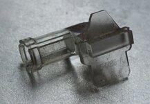
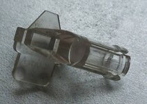
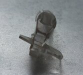
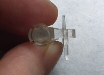
So next step is to wait for my new ZuluSCSI and get an operating system loaded. Oh, and for the ZuluSCSI, I made a custom drive slot cover (3d printed) with a slot for the drive activity LED. The LED holder I also 3d printed using clear PETG. Just needs to get painted now before installing:

So far so good. Next step is the OS and hopefully I don't run into any issues. Oh and I still have to inspect and probably repair the 800K floppy drive.
Picked up a Macintosh II from a forum member a few weeks back. It had been sitting for a decade and in order to preserve it, most of the caps had been removed as well as the batteries. So it was project from the beginning. The case was a bit yellow but physically it looked to be in decent shape.
TL;DR - Before getting into the details, here she is as of this afternoon. Looking sharp. Currently plays its boot chime and shows the blinking disk icon, which is a good sign for the repairs thus far. I am in the process of getting another ZuluSCSI for it.
Inspection
First step was to inspect the motherboard. The previous owner mentioned there was some damage near the power switch and sure enough there was an obvious broken trace there. Scanning the board, there was the usual green funk from capacitor goo on chips near where the capacitors were. Almost every capacitor had leaked at some point. The rest of the chips on the motherboard seemed to be in good shape with bright shiny legs. Multiple traces near each capacitor location had some evidence of corrosion so I had to scrape off the corrosion and some of the solder mask to be sure.
There was corrosion in each of the blue circles but no trace damage. And there was trace damage in each of the red circles - continuity was broken in those spots.
Trace Repair
I scraped off the corrosion, resealed it with some clear coat, and for the broken traces, routed around the damage with new wiring.
Capacitor Replacement
The board is a revision B board. 14 of the capacitor locations had both through holes for axial capacitors or pads for surface mounted caps. I'm actually not sure how these revision B boards were shipped from the factory, with surface mounted capacitors or with axial capacitors. On this particular motherboard, the pads were clean (didn't look used) and the through holes were clearly used and had remnants of the legs from the capacitors that had been cut off. Four of the axial capacitors remained on the board. I purchased 16V 47uF and 16V 10uF tantalum caps for the 14 locations with pads. The four remaining axial capacitors I cut off and replaced with fresh axial capacitors.
Batteries
I read that the Macintosh II requires two batteries to even start. Looking at the Guide to the Macintosh Family Hardware, the soft power signal is sent using power from these batteries. This differs from the IIci / IIcx which use the trickle power from the PSU. Rather than going with a full size battery, I decided to try two CR2032 batteries instead. I purchased some CR2032 battery mounts. The picture was with temporary wires on them as I wanted to ensure it would work first. It did work.
First Boot Attempt
With the capacitors on the board, I made a first attempt to boot up the Macintosh II. Failed. Nothing happened when pressing the power button. I thought perhaps the CR2032s weren't going to work. I looked up the pinout for the PSU to motherboard connector:
Pin 15 should be the signal from the motherboard when the power button is pressed. I used a multimeter to test pin 15 and I was getting voltage when the power button was pressed. So it looked like the CR2032s were fine and something was wrong with the power supply. I opened up the power supply:
I poked around with my multimeter, tried simulating the soft power signal, I got nothing. I could have debugged some more but it wasn't worth it because I was planning to do another ATX power supply conversion so I decided to move on with that.
Power Supply Conversion
I took the specs on the Astec power supply and found a donor ATX power supply on Amazon. I settled on a Coolmax I-400 400W power supply. The only spec that was off was the -12V which only had 0.8A vs the 1.0A on the stock power supply. Having done this conversion on my IIci and Quadra 700 before and had no issues with even 0.6A, I decided to go for it. Here's the donor PSU:
I had heatshrinked the wires I didn't need but later soldered them off the board for cleanness. Next step was to remove the old power supply but save the power ports.
In order to save the passthrough power for the monitor, I had to save the Omron relay and so soldered it off the old power supply:
I could have purchased a new one but this one was working fine. Next step was to drill four new holes into the PSU enclosure to mount the new power supply.
and with the new standoffs mounted:
After that, it was handling the wiring. Here's a table:
- Pin 1 Mac (+12V) - Pin 10 Yellow on the ATX connector.
- Pin 2-6 Mac (+5V) - Pin 4, 6, 19, 20 Red + one Red on the secondary 4pin plug on the ATX connector.
- Pin 7-12 Mac (GND) - Pin 3, 5, 7, 13, 15, 16 Black on the ATX connector.
- Pin 14 Mac (-12V) - Pin 12 Blue on the ATX connector.
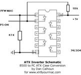
- Pin 15 Mac (/PFW) - Send to the base of a 2N2222 transistor with a 10K ohm resistor in between.
- Emitter on 2N2222 Transistor - Pin 17 Black on the ATX connector.
- Collector on 2N2222 Transistor - Pin 14 Green on the ATX connector (PS_ON), followed by a 1K ohm resistor, followed by Pin 9 Purple on the ATX connector (+5VSB).
- Also took a 3.3V line off the ATX power supply to drive the Macintosh II PSU's LED.
Also added a Noctua fan while I was in there. Reassembled the power supply and then powered it up. Good light on the PSU and I hear the boot chime as well as I see the blinking question mark disk icon. Yes!
Here's the motherboard and PSU back inside the case:
So next step is to wait for my new ZuluSCSI and get an operating system loaded. Oh, and for the ZuluSCSI, I made a custom drive slot cover (3d printed) with a slot for the drive activity LED. The LED holder I also 3d printed using clear PETG. Just needs to get painted now before installing:
So far so good. Next step is the OS and hopefully I don't run into any issues. Oh and I still have to inspect and probably repair the 800K floppy drive.