Andres99907
Member
Some time ago I posted a thread where I talked about my Mac IICX having a short circuit, which was a false positive, investigating further, it may be that multimeters give short measurements under low resistances like Apple's 16 Ohms logic boards.
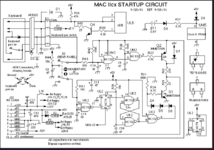
And during all that time I tested different components of the computer's startup circuit.


I have a list of things that should be in order:
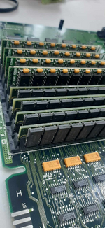
- The ram slots are fully occupied and are of two different capacities.
- The PRAM battery outputs 3.2V.
- The Switch S3 is working.
- The caps were replaced with new ones of the same capacity but TEAPO caps.
However I have some questions that I have not been able to resolve and I need help with them
- How can I test the PSU as I do with ATX power supplies.
- Should the C16 capacitor be charged up to 5V?
Suspicious things:
- When the Switch S3 is activated, the capacitor C16 discharges, however it is probably to activate another component so it doesn't matter much.
- There is no continuity between R28 and R29 with pin 9 of connector J22, not sure if there should be continuity, however they are connected in the diagram.
- When I test the power supply it outputs 5.1V directly, but on the caps I see 4.3V.
I've been trying to solve the problem for some time but I haven't been able to I'd like to at least test the power supply to see if it works, or maybe replace it with an ATX one.
And during all that time I tested different components of the computer's startup circuit.


I have a list of things that should be in order:
- The ram slots are fully occupied and are of two different capacities.
- The PRAM battery outputs 3.2V.
- The Switch S3 is working.
- The caps were replaced with new ones of the same capacity but TEAPO caps.
However I have some questions that I have not been able to resolve and I need help with them
- How can I test the PSU as I do with ATX power supplies.
- Should the C16 capacitor be charged up to 5V?
Suspicious things:
- When the Switch S3 is activated, the capacitor C16 discharges, however it is probably to activate another component so it doesn't matter much.
- There is no continuity between R28 and R29 with pin 9 of connector J22, not sure if there should be continuity, however they are connected in the diagram.
- When I test the power supply it outputs 5.1V directly, but on the caps I see 4.3V.
I've been trying to solve the problem for some time but I haven't been able to
