flux capacitor
Member
Hi all.
This is my very first post, and it's going to be a long one. But I hope it will be of some value for anyone facing a situation similar to the one I found myself in. There are images some viewers might find disturbing, but don't worry, there is a happy ending.
Preface (skip, if you aren't into karma-will-bite-you-in-the-ass-stories):
I recently attended a retro-computing-talk (given by a colleague of mine) at a tech conference (held by the company I work for), and instead of being a good puppy and keeping my stupid trap shut at the q&a, I had to be that annoying guy that had a statement instead of a question. Yes, I am appropriately ashamed of myself for that one.
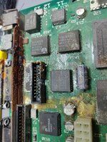
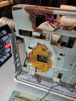
So, I held my little sermon about how you should always remove batteries and suspect caps from old computers if you are going to put them away for storage, but actually I was just being a smart ass who has seen a bunch of Adrian's digital basement videos. I totally didn't practice what I preached there, and my guilty conscience ate away at me for a few days, so when I finally worked up the courage to dig out my own SE/30 that I carelessly shoved into the remotest corner of my basement years ago, I got what I deserved.
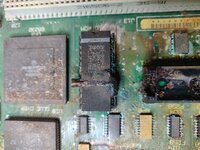
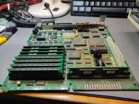
Actual repair story:
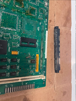
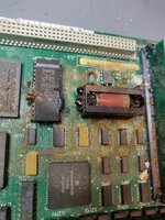
At first I thought it was a goner, but after a good soak in vinegar and a ride in the dishwasher (yes, I know, this topic is quite controversial, but it was a judgement call and I didn't feel like laboriously q-tip-cleaning something that was most probably going to go in the trash anyways) things didn't look so dire (see other attached pictures). The video ROM was beyond rescue, but as far as visibly damaged chips were concerned, that was about it. The RTC looked like a lost cause, too, but it cleaned up nicely and actually still works. Other than that, there were "only" a few vias and through holes eaten away, mostly around the video ROM chip.
That was when I changed my mind from "save it for parts" to "challenge accepted".
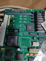
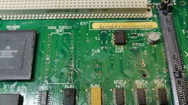
So after first sinking a bit more money into the project by recapping the whole thing including PSU and analog board, I did what one does, who has a busted old computer they know absolutely nothing about: Watch more youtube videos. And google the schematics, maybe.
After first taking all the suspect chips off the board, cleaning and testing them where possible (surprisingly, all the logic chips and resistor packs tested OK), putting them back on the board, then roughly learning about what goes where and buzzing out and bodging up all the visibly broken traces, I put everything together for a first smoke test and got the fan running, and that was it.
I took everything back apart and checked the PSU by itself and all voltages were OK under light load. I then started to poke around on the logic board and was amazed to find a video signal, so I put everything back together and was greeted with a simasimac, although I was only just learning what that was or what it meant to many people that encountered it. At about that point I started to search this forum directly, since most results from my regular search engine pointed here, anyway.
After finding better schematics and systematically checking all data and address lines, finding and fixing a few more broken ones in the process, learning about the address-bus-walk the CPU does with no ROM present, and confirming it actually does it, I still had a chime of death and a simasimac screen.
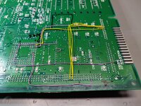
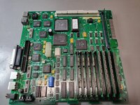
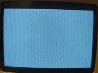
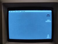
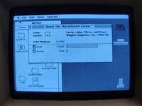
Since I had to replace the video ROM, I suspected something was still wrong in that neighborhood. As I was poking around the video circuitry I noticed that the Video ROM wasn't getting selected at all, but I had no idea why. The enable/select signal for the Video ROM is generated by UE6, which is a PAL, so it was hard to tell if the chip itself was at fault or if it just wasn't receiving the correct input signals. As it was located in a mostly undamaged area of the board, and I haven't found much information on these PAL chips going bad, I proceeded to look at its inputs and found that the RW signal wasn't doing much, either. That looked to be coming from the GLUE chip, and I have definitively been messing with that one. I had previously taken it off the board to clean it, because it had a blotch of battery gunk on a few pins, which I was afraid was going to keep festering underneath if not addressed. Upon re-inspecting my solder job, I found three unconnected pins, which turned out to be the last missing piece of this puzzle, because after fixing them, i was pleasantly surprised by a happy mac chime and the question-mark-disk-icon. And after removing the initiator-config from my bluescsi.ini, I had a fully functional SE/30 again!
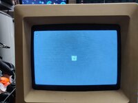
So, what am I trying to sell here? That it's easy to bring a computer back to life that looked like something that would attack you in "The last of us"? Certainly not! But it also isn't impossible, if you have a general understanding of electronics, good resources, the right tools and an insane amount of determination.
While I'm not qualified to comment on my own skills or determination, I do want to say a few more words about the tools and resources I used on this project.
So, here is a list of the most essential tools and consumables:
The award for most time-saving resource goes to the two tables on the last pages of this schematic. Those, and three text markers, helped tremendously with buzzing out all the data and address bus connections. JDW's mouser baskets for the capacitors on the analog board and power supply were also very convenient.
One thing I really would have loved to have would have been some kind of dedicated diagnostic ROM, or even a better understanding how the POST on these machines actually works. What is tested/enabled in which order, and where exactly during these steps does my machine branch to the chime of death, was a question I would have loved an answer for. In hindsight, I'm not even sure if that would have really helped with finding this particular problem, but it sure would have been nice to have at the time.
Which brings me to this place, right here, 68kmla.org. This site was crucial in understanding how these computers work and which failure mode pointed to which problem, especially regarding these "modern" failure modes, caused by battery and capacitor damage. The classical literature (dead mac scrolls et al) was of surprisingly little help with that, actually, because those books mostly focus on problems that occurred with these machines when they were new, like single broken parts, or cracked solder joints. Not a battery that blew up five years ago and let its caustic goo slowly munch away at your logic board.
So, all there's left to do is to say "Thank you!" to all the people here (and the other forums, also youtube), who've lived through these problems before, perhaps with less lucky outcomes, and now use their experience to help others. Thank you all sincerely!
This is my very first post, and it's going to be a long one. But I hope it will be of some value for anyone facing a situation similar to the one I found myself in. There are images some viewers might find disturbing, but don't worry, there is a happy ending.
Preface (skip, if you aren't into karma-will-bite-you-in-the-ass-stories):
I recently attended a retro-computing-talk (given by a colleague of mine) at a tech conference (held by the company I work for), and instead of being a good puppy and keeping my stupid trap shut at the q&a, I had to be that annoying guy that had a statement instead of a question. Yes, I am appropriately ashamed of myself for that one.
So, I held my little sermon about how you should always remove batteries and suspect caps from old computers if you are going to put them away for storage, but actually I was just being a smart ass who has seen a bunch of Adrian's digital basement videos. I totally didn't practice what I preached there, and my guilty conscience ate away at me for a few days, so when I finally worked up the courage to dig out my own SE/30 that I carelessly shoved into the remotest corner of my basement years ago, I got what I deserved.


Actual repair story:
At first I thought it was a goner, but after a good soak in vinegar and a ride in the dishwasher (yes, I know, this topic is quite controversial, but it was a judgement call and I didn't feel like laboriously q-tip-cleaning something that was most probably going to go in the trash anyways) things didn't look so dire (see other attached pictures). The video ROM was beyond rescue, but as far as visibly damaged chips were concerned, that was about it. The RTC looked like a lost cause, too, but it cleaned up nicely and actually still works. Other than that, there were "only" a few vias and through holes eaten away, mostly around the video ROM chip.
That was when I changed my mind from "save it for parts" to "challenge accepted".


So after first sinking a bit more money into the project by recapping the whole thing including PSU and analog board, I did what one does, who has a busted old computer they know absolutely nothing about: Watch more youtube videos. And google the schematics, maybe.
After first taking all the suspect chips off the board, cleaning and testing them where possible (surprisingly, all the logic chips and resistor packs tested OK), putting them back on the board, then roughly learning about what goes where and buzzing out and bodging up all the visibly broken traces, I put everything together for a first smoke test and got the fan running, and that was it.
I took everything back apart and checked the PSU by itself and all voltages were OK under light load. I then started to poke around on the logic board and was amazed to find a video signal, so I put everything back together and was greeted with a simasimac, although I was only just learning what that was or what it meant to many people that encountered it. At about that point I started to search this forum directly, since most results from my regular search engine pointed here, anyway.
After finding better schematics and systematically checking all data and address lines, finding and fixing a few more broken ones in the process, learning about the address-bus-walk the CPU does with no ROM present, and confirming it actually does it, I still had a chime of death and a simasimac screen.


Since I had to replace the video ROM, I suspected something was still wrong in that neighborhood. As I was poking around the video circuitry I noticed that the Video ROM wasn't getting selected at all, but I had no idea why. The enable/select signal for the Video ROM is generated by UE6, which is a PAL, so it was hard to tell if the chip itself was at fault or if it just wasn't receiving the correct input signals. As it was located in a mostly undamaged area of the board, and I haven't found much information on these PAL chips going bad, I proceeded to look at its inputs and found that the RW signal wasn't doing much, either. That looked to be coming from the GLUE chip, and I have definitively been messing with that one. I had previously taken it off the board to clean it, because it had a blotch of battery gunk on a few pins, which I was afraid was going to keep festering underneath if not addressed. Upon re-inspecting my solder job, I found three unconnected pins, which turned out to be the last missing piece of this puzzle, because after fixing them, i was pleasantly surprised by a happy mac chime and the question-mark-disk-icon. And after removing the initiator-config from my bluescsi.ini, I had a fully functional SE/30 again!


So, what am I trying to sell here? That it's easy to bring a computer back to life that looked like something that would attack you in "The last of us"? Certainly not! But it also isn't impossible, if you have a general understanding of electronics, good resources, the right tools and an insane amount of determination.
While I'm not qualified to comment on my own skills or determination, I do want to say a few more words about the tools and resources I used on this project.
So, here is a list of the most essential tools and consumables:
- At least one proper soldering iron. More is better, because these boards can sink a lot of heat. If you are looking to buy your first iron, get a pinecil.
- Good quality leaded solder. It is easier to use than lead-free and the original solder on these old boards is leaded anyway.
- Basic electronics tools. Side-cutters (it pays to spend a bit more on these), tweezers, and a knock-off I-fix-it screwdriver kit.
- A multimeter. For a job like this, any cheap thing with a continuity-beeper will do. Again, more money will buy nicer things.
- Good illumination and magnification. This gets more important with the operator's age. Can be anything from a monocle or Adrian Black's headgear to a Mantis Vision, with amscopes and usb-microscopes somewhere in the middle.
- Good quality flux, and a lot of it! (seems obvious, but I've seen so many people on youtube try to do stuff like removing bridges from PLCC or QFP packages without it, so it's worth mentioning) If in doubt, use more flux!
- Solder Wick, and also lots of it. I must have gone through several meters of the stuff.
- ChipQuik low melting point solder. This stuff is invaluable in taking (old and fragile) chips off the board. Has to be thoroughly cleaned up, though.
- A boatload of q-tips and isopropanol. Also white vinegar, as well as an assortment of brushes, blades, prying, poking, rubbing, scrubbing, scraping, and picking tools...
- Wire-wrapping-wire.
- An ATX extension cable.
- An oscilloscope. Maybe a logic tester would have done, but I don't own one, so I can't tell. Also, and I have to steal a quote here: "Even though, we are looking at digital signals, the integrity of these signals needs to be looked at in the analog domain." Anything as fast as the fastest clock/signal on your board will do.
- The tongue sticking out at exactly the right angle, and two months worth of "careful" and "easy does it".
- And a shit-ton of the purest, finest and stupidest dumb luck. Luck that all the custom chips were alright, and even more luck that I somehow managed to not make it any worse.
The award for most time-saving resource goes to the two tables on the last pages of this schematic. Those, and three text markers, helped tremendously with buzzing out all the data and address bus connections. JDW's mouser baskets for the capacitors on the analog board and power supply were also very convenient.
One thing I really would have loved to have would have been some kind of dedicated diagnostic ROM, or even a better understanding how the POST on these machines actually works. What is tested/enabled in which order, and where exactly during these steps does my machine branch to the chime of death, was a question I would have loved an answer for. In hindsight, I'm not even sure if that would have really helped with finding this particular problem, but it sure would have been nice to have at the time.
Which brings me to this place, right here, 68kmla.org. This site was crucial in understanding how these computers work and which failure mode pointed to which problem, especially regarding these "modern" failure modes, caused by battery and capacitor damage. The classical literature (dead mac scrolls et al) was of surprisingly little help with that, actually, because those books mostly focus on problems that occurred with these machines when they were new, like single broken parts, or cracked solder joints. Not a battery that blew up five years ago and let its caustic goo slowly munch away at your logic board.
So, all there's left to do is to say "Thank you!" to all the people here (and the other forums, also youtube), who've lived through these problems before, perhaps with less lucky outcomes, and now use their experience to help others. Thank you all sincerely!

