• Updated 2023-07-12: Hello, Guest! Welcome back, and be sure to check out this follow-up post about our outage a week or so ago.

Mac SE Monitor On/Off Switch

hfrazier

Well-known member
Hi Everyone,

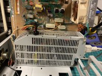
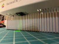
I would like to present my SE/30 monitor on/off switch. It's only a matter of removing two jumper wires on the analog board - W4 and W5 - and switching each of them on either pole of a DPST switch. (With optional LED, DigiKey P/N CKN2068-ND). Full instructions and more photos here in the album: https://imgur.com/gallery/m4IMHGU
QVWQspt.jpg

S44aiXn.jpg

 
Last edited by a moderator:

LaPorta

Well-known member
Nice job with that! Two devils advocate questions:

-Why do that when you can just turn the brightness down?

-Does that involve making a hole in an otherwise pristine case?


hfrazier

Well-known member
Nice job with that! Two devils advocate questions:

-Why do that when you can just turn the brightness down?

-Does that involve making a hole in an otherwise pristine case?
Good questions!

Yes, you  will have to cut the case and some of the inner metal chassis. ...but the SE/30's are so awesomely hackable, why not? If you wish to run it as a server, the switch is fairly inconspicuous.

As for the reasoning... (besides bringing power consumption down to 34W from 47W)

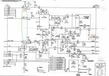
When you turn down the brightness, all you do is save the screen from burn-in. The filament of the CRT is still powered and thus slowly burning up, and the flyback and horizontal/vertical deflectors are still running, consuming power (and shortening their lifespan.) This switch effectively cuts power to U1 which buffers the video signal going in to the driver circuitry and also cuts power to the CRT filament. The red circles are where the jumper wires are and the green circle is all of U1:

AB_mod.png

 
Last edited by a moderator:

techknight

Well-known member
Wouldnt it have just been easier/safer to put a switch in the sweep supply at pin10 on P3?

You will blow out that 74LS IC eventually doing it the way you are doing it. 

At minimum you need a Zener diode, a resistor, and capacitor filter network now at the IC. Just C23 alone isnt good enough anymore now that you have wires running half way to China and back, along with EMI generated by the switch, which is now closely coupled with the 12V line. All kinds of bad here.

But hey, at least you tried. :)

 
Last edited by a moderator:

hfrazier

Well-known member
Wouldnt it have just been easier/safer to put a switch in the sweep supply at pin10 on P3?
I tried that first, actually. Switching it back on made the logic board brownout and reset.

You will blow out that 74LS IC eventually doing it the way you are doing it. 
You are probably right, let's add those. Can you show me where to make those mods and I will add it to my original post so we can make the mod better?

Side note- I thought about using a piece of hollowed coax cable.. but thought that the twisted pair would be good enough for EMI.

 
Last edited by a moderator:

techknight

Well-known member
you just need to tack a couple capacitors. 0.1uf ceramic/film, and 1uf electrolytic. across the VCC/GND lines directly at the chip. Also, a 5.6V Zener diode with the stripe side of the diode body soldered on the VCC pin, and other lead to ground. 

Then, put a 10 ohm resistor between the wire coming in from the switch, and the chip's VCC where all the above parts are attached. this will serve as a dump resistor if something were to overvolt or short causing the zener diode to clamp. You could go with the metal film non flammable type here. Maybe fusible type so it pops open if failure. 

 
Last edited by a moderator:

IlikeTech

Well-known member
I would figure that if your board is browning out you might need to recap the power supply, which if you are leaving it on to run as a server is probably a good idea to do anyway.  Just killing the sweep voltage seems like the safest thing to do in this case.


error1

Active member
I wonder how hard it would be to take it further and automatically turn the screen off and on based on the video signal, switching the sweep voltage off if there's not a single bright pixel detected in 20 seconds or something. DIY DPMS :)


jimjimx

Well-known member
Interesting, and I as well wondered about the stability of the 7438 when being re energized..

I also wonder about the cathode as the filament reheats. I’d hate to lose the CRT.  Can’t get the gun replaced cheaply!!

....I might give this a try.  But, it’s 2am right now, and don’t know what I’m thinking.


hfrazier

Well-known member
I would figure that if your board is browning out you might need to recap the power supply, which if you are leaving it on to run as a server is probably a good idea to do anyway.  Just killing the sweep voltage seems like the safest thing to do in this case.
I have actually recapped the PSU and Analog board... The inrush current to all the larger value caps on the Horizontal/Vertical circuitry is what causes it to brown-out for a second. A diode and a some larger caps on the logic board might fix this, but I found that powering off the buffer chip was more elegant.

I wonder how hard it would be to take it further and automatically turn the screen off and on based on the video signal, switching the sweep voltage off if there's not a single bright pixel detected in 20 seconds or something. DIY DPMS :)
YES! Or maybe a little Arduino circuit that monitors the ADB circuit for mouse/keyboard activity...  }:)

Interesting, and I as well wondered about the stability of the 7438 when being re energized..

I also wonder about the cathode as the filament reheats. I’d hate to lose the CRT.  Can’t get the gun replaced cheaply!!

....I might give this a try.  But, it’s 2am right now, and don’t know what I’m thinking.
I bet a NTC Thermistor would work.. Never use them before but maybe?

 
Last edited by a moderator:

IlikeTech

Well-known member
Sorry, was typing in a hurry.  You should make your switch open the CRT filament with a relay, which will greatly save hours on the gun.


techknight

Well-known member
I would have to refer back to the schematic as I do not remember. But...

Is the CRT Filament powered by the flyback? if so then simply cutting off the horizontal drive would simply fix that. 


hfrazier

Well-known member
Also, you need to open the filament of the CRT!


Sorry, was typing in a hurry.  You should make your switch open the CRT filament with a relay, which will greatly save hours on the gun.
Yep. The second pole of the switch does that. If you look at the photos and then the schematics, you'll notice that there are two jumpers that have been replaced with wires to the switch. :)

 
Last edited by a moderator:

jimjimx

Well-known member
I would have to refer back to the schematic as I do not remember. But...

Is the CRT Filament powered by the flyback? if so then simply cutting off the horizontal drive would simply fix that. 
I’m not sure, but pretty sure, the filament is 12v, as it’s just a heater for the cathode, like all tubes, but different filament voltages.


techknight

Well-known member
I know its a heater for the cathode. I also know its 12v. actually, its 12.6V 

Some CRTs are 6.3V 

Some are powered from the flyback transformer with AC. Some are powered from a DC regulator. 

I just dont remember which is applicable here. 


ttb

Well-known member
I'm glad to see someone's tried this. I was looking at just switching the 12V sweep so thanks for the advance troubleshooting!

Ideally I'm hoping to use a switched potentiometer to replace the brightness knob with one that has a detent below minimum brightness to fully turn the monitor off. So far all of the ones I've found are a bit too deep to fit without cutting the power supply enclosure but I'd rather do that to preserve the stock external appearance so we'll see.

 
Top