• Updated 2023-07-12: Hello, Guest! Welcome back, and be sure to check out this follow-up post about our outage a week or so ago.

Macintosh SE/30 logicboard recreation (thread revival)

cheesestraws

Well-known member
But this theory is thrown off by the other set of symptoms on the same 3 boards with a different revision of PAL chips fitted

You're thinking about this backwards. If three different symptoms occur but there's one underlying problem, the cause is related to all of them. So it's not a waste of time to be diagnosing any of them: so start with the symptom that is most regular.
 

croissantking

Well-known member
Are those columns corrupted after looking OK, or do they never get proper data? I'm sort of assuming the second, a rather deterministic behavior.
I’m not sure if I understand your question correctly - but the behaviour is such that the machine can run for a while and not show any corruption on those columns. At some point (sometimes hours, but more often minutes after powering on) the little horizontal lines start to generate in those columns, gradually building up whenever there is movement on-screen and usually following the mouse pointer.

Where did you buy your logic chips? How did you pick them?
Mouser, but it’s moot. One of my boards uses all original donor parts.

Check your resistor and capacitor values, pull up / down values.
I used pick and place for the backside passives. Any chance these could have been incorrectly selected? Is it worth desoldering and checking all values?

Have you made any component substitutions?
The first reloaded board doesn’t have, but in case it’s relevant the donor parts are a mixture of components from two different SE/30 boards.

The other two reloaded boards have new F253/LS30/LS166/LS393 etc. All larger chips - the DIPs and PLCCs - are 100% original.
 

Phipli

Well-known member
I’m not sure if I understand your question correctly - but the behaviour is such that the machine can run for a while and not show any corruption on those columns. But at some point (sometimes hours, but more often minutes after powering on) the little horizontal lines start to generate in those columns, gradually building up whenever there is movement on-screen and usually following the mouse pointer.
Wait, are you saying it doesn't do it for hours? Are you running them outside the case?

Does it do it if you point a fan at it?
 

croissantking

Well-known member
Wait, are you saying it doesn't do it for hours? Are you running them outside the case?

Does it do it if you point a fan at it?
It’s rare that the fault takes hours to show, it usually happens faster than that. But it does vary. There is also a difference in terms of behaviour between my three builds - one of them appears to exhibit the symptoms more frequently and more severely than the other two.

I’ve run the boards properly fitted inside of a case and also outside.

Will try the fan.
 

Phipli

Well-known member
Out of interest (and wanting to know more about how such things are fabricated), why do you say that?
Because they are a professional business that make boards, all day, every day. It is not in their interest to get things wrong, and if they were, they'd have already invested money and time to sort it. These boards are trivial to make compared to some of the stuff they'd be asked to make.

We all can't understand why things aren't working sometimes, but it is almost never the parts we use, but decisions, misunderstandings or mistakes we have made along the way. You're talking like the three boards are three independent cases, but there are multiple common factors - some components, some parts selection, and the methods you've used. You might have cooked a chip on all three, or solderbridged a via on all three, or used an LS where you should have used an F series logic chip. Did you make an error on the first and copy the first board for the other two? Have you used the same PSU on all three?

Its a probability thing - has a company that has a good reputation made an error on three boards in a row, or, have you? Not meaning to be mean, but unless you are a professional batch assembly person and these are exceptionally wild circumstances, you're really looking to work out where you went wrong.

Really sorry, it sounds like I'm questioning your ability, but I'm not - I'm just saying that manufacturers are on a different level to us hobbyists. My stuff doesn't work all the time, but I've been in that situation enough to say while technically possible that a manufacturer could have messed up, it has always being something I have done.
 

Phipli

Well-known member
Out of interest (and wanting to know more about how such things are fabricated), why do you say that?
The board itself is created using lithography and is tested automatically using probes to ensure that there aren't unexpected shorts. Components are placed by a pick and place machine (a robot) - components are lined up on big reels with labels on them. Cameras are used to inspect the PCB and fitted components to ensure that they visually look like they should and aren't in the wrong place. A human inspection is also done.

There are videos showing the Seeed Studio and JLCPCB factories on youtube... let me see...


Phipli

Well-known member
Where I have selected new ICs, they are the following. Do these all seem OK?

UB12, UC12: SN75175DE4
UD1: SN74F240DW
UA9: TL071CDR
UF8, UG8: SN74LS393DR
UE8: SN74LS166ADR
UJ6: SN74LS30DR
RP9: 4816P-T02-221LF
RP1, RP4, RP5, RP6: 4816P-T01-220LF
RP7, RP8: 4816P-T02-102LF
UI2, UI3, UI4, UJ2, UJ3, UJ4: SN74F258D
UA8, UB8, UC8, UD8: 595-SN74F253DR
RP2, RP3, RP10: 4120R-601-250/201L
For the most part, the letters at the end can be ignored because they usually relate to the package (i.e. DIP) and packing (paper tape etc.).

So what you're concentrating on is are the letters in the middle the same as the original parts - "LS", "F" etc. Similarly, if any parts have a speed grade.
 

cchiro

New member
Hi,
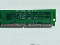
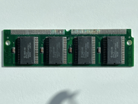
Is this ROM saveable?
I am getting started rebuilding a battery damaged SE/30 and this is what the ROM looks like.
I have no way of testing it and am wondering if it has a chance of working in a rebuild.
Any feedback will be greately appreciated. Thanks!
tempImageWRPRM8.pngtempImageKgZtu5.png
 

CircuitBored

Well-known member
@cchiro I'm curious as to how you get on with this. I have three battery-bombed ROM SIMMs, all different physical versions, that don't work despite my best efforts to save them. I initially thought they were just simple two-layer boards but it turns out that at least two of them are four-layer. I'll probably end up designing replacement PCBs and then discovering that the chips themselves are toast...
 

robin-fo

Well-known member
My slightly battery-damaged SE/30 SIMM still works fine after cleaning the pads with flux/solder/solder braid.

Or maybe just re-flash a rominator? 😇
 

croissantking

Well-known member
Time for an update on my Bolle board shenanigans.

I've built 3 of them - and they all have the same intermittent graphical problem that I can't solve. Depending on which version of the PALs I have fitted at UE6 and UE7 (either 341-0637-A + 341-0688-A, or 341-0754A + 341-0755-A) the symptoms will exhibit quite differently, which originally led me to believe one of my boards had a problem unrelated to that of the other two.

I'm really asking myself if the reloaded boards from JLCPCB I have are from a faulty batch. It's hard to conclude anything else. But how likely is this?


With the 06xx PALs - horizontal flashing streaks of corruption are exhibited whenever there is movement onscreen but they do not stay on-screen.

View attachment 60115

With the 07xx PALs - vertical columns of corruption build up and remain on-screen.

View attachment 60116

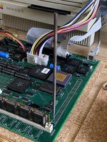
I’ve found out that if I make contact with pin 6 of UE7, the issue clears up immediately.

What I mean is that I’m poking at it with a thin pointy metal file.

This pin is labelled ‘Nubus’ and connects to pin 33 of the Glue chip, and pin 82 of the PDS slot. I can make contact at any of these locations and it fixes the problem for as long as I hold down on it.

IMG_3541.jpeg

With this file wedged here, I don’t even need to touch it for the issues to go away. With a smaller metal item like a paperclip, I do need to touch it.

What is touching it doing to the circuit - am I adding a resistive path to ground?

Other thoughts?
 
Top