• Updated 2023-07-12: Hello, Guest! Welcome back, and be sure to check out this follow-up post about our outage a week or so ago.

SuperMac Spectrum/24 Series III Display Artifact Issue

MacOSMonkey

Well-known member
Nice - you could try just sucking out all the old solder on that device and resoldering it. Also, when the solder is out, remove the PAL/GAL and check the path from the vias to the connector / other devices.
 

jmacz

Well-known member
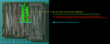
I can consistently 'fix' the issue by heating that one of the two green squares (the one closer to the center of the daughterboard). No other quadrant does anything.. just that one and a little bit the other green one under it.

Nice - you could try just sucking out all the old solder on that device and resoldering it. Also, when the solder is out, remove the PAL/GAL and check the path from the vias to the connector / other devices.

Cool, will do. Hopefully this is getting me closer to solving this one.
 

jmacz

Well-known member
daughterboard pins.jpg

Haven't had a chance to take any of the chips (PAL/GAL) off yet. But did check continuity on the pins in that area. The board seems to be 3 layers: traces on the top side of the board, traces on the bottom side of the board, and traces sandwiched in the middle that you can see with a good light underneath the surface. Was fairly easy to trace each pin (top side, bottom side, middle layer). But the two red pins, I can't see traces (top, middle, bottom) coming from them (and they aren't connected to each other). Also tried checking those two pins against every other pin on the daughter board and I get no continuity. Every component on this daugtherboard is through hole so I figure if they are connected at all, it has to be to something on this board. They could of course not be connected.

Anyhow, will pull both chip 5 and chip 4 on the bottom row sometime this week (work permitting). I did repro the heat test a bunch more times though.. it's always in that yellow dotted box region where heat fixes the issue temporarily.

I hope it's not the chip itself. Because not sure what I can do at that point since they are unmarked.
 

jmacz

Well-known member
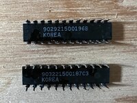
Took the two chips off. Didn't see anything remarkable underneath the chips. The chips physically appear to be ok. The bottom of each chip had what appears to be a serial number. But no other identifying marks.

IMG_4535.JPG

With the chips out of the way, will look at the board in more detail to see if I can determine if those two pins really were left disconnected or if I can get a better view where they might be going. Keeping my fingers crossed that they indeed go somewhere and the fact that I was not able to determine where using continuity testing, that those are the cause of my issue.
 

MacOSMonkey

Well-known member
Don't mix them up. o_O If you heated that area and it resolved the problem and those 2 pins were still testing as no-connects when the board was warm/working correctly, then that's probably not the issue. But, continuity might show something. Otherwise, you are down to things like: residual bad solder (previously) -- which you can infer after you re-solder the parts if the board no longer fails, or it could be a device bond wire/packaging issue or some other device issue (if not an intermittent pcb connection).
 

Bolle

Well-known member
I’d say Lattice GALs from that bottom shot… have seen quite a few of them with similar markings.
If they are they can possibly be glitched to read even with the security fuse set.
Could be either 20V8 (very likely to be readable) or 22V10 (reads sometimes) in that DIP24 packaging.
So there’s hope to save the board even if they are on their way out.
 

jmacz

Well-known member
Don't mix them up. o_O If you heated that area and it resolved the problem and those 2 pins were still testing as no-connects when the board was warm/working correctly, then that's probably not the issue. But, continuity might show something. Otherwise, you are down to things like: residual bad solder (previously) -- which you can infer after you re-solder the parts if the board no longer fails, or it could be a device bond wire/packaging issue or some other device issue (if not an intermittent pcb connection).

Yup, I marked the chips with a sticker on top to ensure I don't mix the two :)

I’d say Lattice GALs from that bottom shot… have seen quite a few of them with similar markings.
If they are they can possibly be glitched to read even with the security fuse set.
Could be either 20V8 (very likely to be readable) or 22V10 (reads sometimes) in that DIP24 packaging.
So there’s hope to save the board even if they are on their way out.

Ok. Ceases to amaze me the wealth of information this community has :) I'm glad there's still some other options in case it does turn out the chips have an issue. But hopefully it's not that.

Thanks guys!
 

MacOSMonkey

Well-known member
Yes! Lattice definitely rings a bell. But, I also think I remember seeing National Semi logos on the original boards -- possibly also the PAL design that later switched to GALs. I reached out to another contact and will try to find out some specifics. The parts are ca. 1988-89.

-> Definitely Lattice parts and programmed in ABEL.
 
Last edited:

jmacz

Well-known member
So if it’s indeed a Lattice 20v8 or 22v10, I would have to buy some and program them, right? If so, I would have to read a good one. Would all of these chips on the daughterboard be the same and thus I would have to read from a good one and then write to a replacement? Or would these be programmed differently?
 

MacOSMonkey

Well-known member
I think they are the same parts. If they are readable, that is the best scenario. But, I am trying to see what I can find out on other fronts. The problem may not be the parts and could be in the pcb. Or if it is definitely the parts, there may be other (harder) solutions - but...it becomes a bigger project.
 

jmacz

Well-known member
So I ended up taking off four chips in that surrounding area. Checked the connections to/from those chips and everything checked out. I then put those chips back on, resoldered them with fresh solder. Tried it out and same problem. And same fix by heating up that same area. Argh.

I still have not figured out those two red pins I mentioned a few posts earlier. I actually left them disconnected when I put the chips back in and they seem to be no-ops. So I suspect they are indeed disconnected or I am not able to exercise them properly. For now I have resoldered those as well instead of leaving them disconnected.

It's quite possible there's a partially broken connection inside the PCB but without knowing where and which pins, not sure where to start.

I've begun a new exercise of laying out where every pin is going. The purpose being if I can find the set of pins that don't seem to be connected while cold, it gives me a shot of heating just those pins and narrowing down further.
 

MacOSMonkey

Well-known member
It could be a device issue...maybe an intermittent wire bond. If you had no change in resistivity on the board connections during cold/hot cycles when depopulated, then it doesn't seem like the PCB. And, if the 2 pins are open whether cold or hot, they are probably no-connects and likely don't matter. Remember that you can have continuity on a resistive/impaired link that beeps on a meter, but that doesn't mean it's good.
 

MacOSMonkey

Well-known member
In terms of no-connects, those pins might be unused inputs. According to the spec, unused inputs should be: 1. tied to adjacent inputs, 2. pulled up to Vcc or 3. pulled down to ground (maybe most likely). So, check continuity to adjacent/power/ground - if one of them is true, then they are unused. If none of them is true and the pins are really unused, then SuperMac didn't follow spec and the unused pins were sources of possible noise injection. You can also tell if they are tied to ground just by looking at the via (which, if device ground vias, should have thermal ties to the ground plane to prevent heatsinking during assembly).

Also, interestingly, the spec on Lattice GAL data retention is "in excess of 20 years." So, it's great that the accelerator still works at 34 years and fair to say that we are now in the "excess" period. ;)
 

jmacz

Well-known member
Screenshot 2023-07-16 at 8.05.58 AM.png

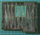
The green pins are Vcc and the red pins are ground. The green shaded areas are the chips that I believe are in question... just based on where I applied the heat. The three chips below the green shaded ones could also be in question given the heat applied is still somewhat close to those areas.

The yellow pins are the ones that seem to be disconnected. At least with the board powered off, they have no continuity to the green pins (Vcc) or red pins (Ground). They don't have continuity to each other. And after multiple passes, neither seem to be tied to any of the other pins on the board. I put the board under a microscope when the chips were still removed, and I could not see anything leading away from the through holes for those pins. That said, I think I was wrong that the PCB only has 3 layers (top, bottom, middle sandwiched in between). There are pins for which I see nothing on the top or bottom surface, or anything perceivable underneath the surface but have connectivity to other parts of the board.

I guess I could try check the voltage to those floating pins when the problem is occurring as well as after heating the area to see if anything changes.

Also, interestingly, the spec on Lattice GAL data retention is "in excess of 20 years." So, it's great that the accelerator still works at 34 years and fair to say that we are now in the "excess" period. ;)

:) hmm, sounds like we need to read those chips just in case.
 

MacOSMonkey

Well-known member
They are probably just no-connect inputs that were never tied low or high. So...what you could do is take those 2 pins and put a 10k axial pull-down on them to ground (put one end of the 10k resistor lead to nearby ground and j-bend the other end and solder it across those 2 pins). Then, if the acceleration still works when warm, they are obviously no-connects. If the problem goes away, then it is possibly because of noise injection from floating inputs plus some age-related change. If acceleration no longer works, then they are not no-connects and something else is going on. Anyway - it's an easy test that tells you everything you need to know about those 2 pins.
 

Bolle

Well-known member
I'd suggest pulling them up instead.
If they're Lattice (or most other manufacturer as well) at least rev B GALs they will have internal pullups.
In case you hit a dead end with the board I'm open to examine it to figure out what type of chips they are and attempt to read/glitch them where possible.
 

jmacz

Well-known member
They are probably just no-connect inputs that were never tied low or high. So...what you could do is take those 2 pins and put a 10k axial pull-down on them to ground (put one end of the 10k resistor lead to nearby ground and j-bend the other end and solder it across those 2 pins). Then, if the acceleration still works when warm, they are obviously no-connects. If the problem goes away, then it is possibly because of noise injection from floating inputs plus some age-related change. If acceleration no longer works, then they are not no-connects and something else is going on. Anyway - it's an easy test that tells you everything you need to know about those 2 pins.

I tried tying them to ground via a 10K resistor, and it didn't change anything (positive effect or negative effect). Still getting the artifacts at millions of colors and still seeing it go away for about 30 seconds or so once that area of the board is heated.

I'd suggest pulling them up instead.
If they're Lattice (or most other manufacturer as well) at least rev B GALs they will have internal pullups.
In case you hit a dead end with the board I'm open to examine it to figure out what type of chips they are and attempt to read/glitch them where possible.

Hmm. Will need your guys help here... what size resistor should I be using to pull up these pins? I checked the Vcc (both on the daughterboard connector as well as pin 24 on the chips -- I believe those GAL 20v8s had Vcc on pin 24) and it's reading around 4.6V.
 

MacOSMonkey

Well-known member
Bolle is (obviously :D ) correct about the internal pull-up.

Here is what the datasheet says:
"The input and I/O pins also have built-in active pull-ups. As a result, floating inputs will float to a TTL high (logic 1). However, Lattice Semiconductor recommends that all unused inputs and tri-stated I/O pins be connected to an adjacent active input, Vcc, or ground. Doing so will tend to improve noise immunity and reduce Icc for the device. (See equivalent input and I/O schematics on the following page.)"

Generally speaking, internal pull-ups (or pull-downs in other devices) are very weak (which is why Lattice makes the additional recommendations) and tying pins high or low usually depends on the application, as long as there is no contraindication for one or the other. In any particular design, you need to consider testing, default state, failure modes, etc. And, for reference, it's usually not a good idea to tie i/o's directly to power or ground -- having the resistor lands or vias makes future rework much easier -- unless you want to start lifting device pins.

However, for this brief test, either high or low is OK and it doesn't really matter (but not disagreeing with Bolle here ). If you're going to leave the resistor in place, then you can probably leave it high, as Bolle suggests. The bottom line is that if you're not seeing any change after tying them to ground, then they are clearly no-connects and you can ignore them. They are not the source of the problem, since there is no change in accelerator behavior...or other scrambled video, etc.

Also, if you are sure that you don't notice any significant relative change in resistivity in the board traces when the board is cold vs. hot, then you are probably looking at a device issue. As before -- it's possibly a bond wire issue...but it could be anything. Maybe one of the cells is marginal - who knows?

If you want to narrow down the specific device, you could try making a heatshield that has an opening the size of 1 device (and downward flaps that isolate around the device and focus the heat. Then, try heating to see if you can narrow it down to a specific device. You're probably going to have to do the test at least 5 times on each of the devices and look at the results. It could be that more than one device is having a problem (?).

If you can pinpoint a specific device, then it might be worth trying to read and replace it, but you will probably have to use the same heating protocol to read it if you want a reliable result, since it is marginal. But, that is easy enough to test when reading (after calibrating the voltage glitch) by reading the part cold and warm to see if there is any difference.

The other extreme option would be to try decapping the package and checking for bonding issues, then repackaging. But, you should only do that after trying to read it, because it could be a destructive process unless managed very carefully. There might be packaging places that could do it with a high probability of success (but without any guarantee that there is a detectable bonding issue).

Anyway - it sounds like you are making progress. And, Bolle's offer to read it is great! Hopefully, the glitch trick could work. I am still trying to check options for you through other channels - no luck yet.
 

jmacz

Well-known member
However, for this brief test, either high or low is OK and it doesn't really matter (but not disagreeing with Bolle here ). If you're going to leave the resistor in place, then you can probably leave it high, as Bolle suggests.

I wasn't planning on leaving it on the board. But for this brief test, I've tried tying to ground. But for trying a test where I tie it to Vcc, what resistor value should I use? Or are you saying just go direct to Vcc for this test?

If you want to narrow down the specific device, you could try making a heatshield that has an opening the size of 1 device (and downward flaps that isolate around the device and focus the heat. Then, try heating to see if you can narrow it down to a specific device.

Great idea! I'll see what I can cook up that will provide enough shielding.
 

jmacz

Well-known member
Also, if you are sure that you don't notice any significant relative change in resistivity in the board traces when the board is cold vs. hot, then you are probably looking at a device issue. As before -- it's possibly a bond wire issue...but it could be anything. Maybe one of the cells is marginal - who knows?

I haven't checked this yet... so many traces on the board that it's like an n^2 problem. Will try to narrow down using the heat shield idea first and then check the resistivity of the traces in that area.

I still agree with you that it's more likely that it's something on the board. The chips are actually on the other side of the PCB when I heat things up (the daughterboard has the underside -- solder joints -- facing outwards. The chips are sandwiched between the mainboard and the daughterboard). And I'm not getting the board that heated when running these tests so I doubt the chips are feeling much of that heat.
 
Top