• Updated 2023-07-12: Hello, Guest! Welcome back, and be sure to check out this follow-up post about our outage a week or so ago.

Radius Pivot IIsi adapter for SE/30 PDS

Trash80toHP_Mini

NIGHT STALKER
You've sort of taken over BadGoldEagle's thread here... :)
Oops.  [:I] ]'>  I was trying to help with that first rendering  .  .  .  then I went waaaay over the top trying to figure out how he could get a second PDS into his project. Sorry, BGE, I'll try to stop now. :-/

 
Last edited by a moderator:

Trash80toHP_Mini

NIGHT STALKER
In addition: apparently I've failed to make it clear that the whole SideCards tangent was an insane Rube Goldberg kinda deal. Yes, I could do it, but i wouldn't! Bolting connectors up to a clear plexi mock-up might be fun to show that it could be done, but there's no way in the world that it should be done.


Trash80toHP_Mini

NIGHT STALKER
I started to apply the KISS principle to the craziness to see if something might come of it and had a breakthrough this morning. So I bounced it off BGE and he said to go ahead and post it.

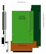
There are several iterations to consider, but here's the version I have mocked up on the plexi blank from another crazy SE/30 project:

BGE-PivotRiser-010.jpg

Couldn't find a good way to mount a slot for one of my NICs in Illustrator, so (in my head, not in hardware) I chopped the bottom 4.75cm off the adapter board, soldering three rows of header pins onto the solder side of the adapter and just plugged the board into the passthru connector of my NIC. Clearances are too tight to do it with a DIN connector, but using headers, the offset sandwiched board just barely clears the drive assembly. Apply electrical tape in true SE/30 hacking tradition and it's good to go.

Fitment at the back of the case is tight as can be, top corner of the Pivot card clear's the Steve's meticulously implemented chamfer on the inside of the case by a few millimeters.  My hybrid, DA-15 Video/10bT/Thinnet breakout board dovetails nicely. I can't use the ferrite ring monster cable from my Pivot SE/30, but any cable built with a solder cup termination connector or IDC variety DA-15 will work a treat.

Could produce just one layout with the 7.5CM extension in place for the NIC deprived. That one would simply have a right angle plug installed for the PDS. If any of the NICless source a compatible Network Card, their board can be scored, snapped off and the headers implemented.

It'd be better to make two versions if it were my choice, but it's not my hack. [;)] ]'>

BGE-PivotRiser-001.PDF

edit: using the taller board without a NIC it's just a regular PDS card bolting directly up to the mounting ears. However, the offset NIC connector board will require something like 1cm thick spacers when bolting it to the mounting ears.

I took some pictures, but those will have to wait for the morning.


Attachments

  • BGE-PivotRiser-001.PDF
    91.8 KB · Views: 62
Last edited by a moderator:

Trash80toHP_Mini

NIGHT STALKER
Come to think of it, you may only need one layout after all. Check with macmetex, if he still has buckets of the SuperMac passive riser cards to go with his Pivot cards, you'll be all set. The SuperMac riser is the perfect stand in for the Asante NIC  .  .  .  after you take a hacksaw to it to remove the sections front and back that interfere with the SE/30 chassis that is.  [}:)] ]'>  No problem, mine worked fine for a while, but I borked something while banging it around testing lot of different board configurations. It's an easy fix, buzz the connections and patch wire any broken traces.

Be that as it may:

Realized last night that I had the pivot card overlapping the NIC PCB and resting nicely on its cable connector. When I was looking at correcting the height by a smidge, interference with the cable on the breakout board was introduced as well as with the raised edge of that pestiferous stock HDD sled. No problem! I fixed that as well by raising the level of the Pivot more than just the thickness of the PCB. Now the ribbon cable tucks neatly between the Pivot Card and the bucket and the Pivot's PCB is located over the sled, clear of its edge..

So we've got the NIC, Adapter and Pivot PCBs overlapping on three different planes. As a nice bonus, the rear mounting bolt hole on the whack angle riser is retained, making for a nice rigid assembly.

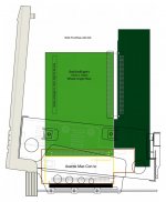
I'm not sure anyone can follow the above, so diagram time! [:)] ]'>

BGE-PivotRiser-015.jpg

The way I've shown the planes is reversed to feature the adapter card, IRL, the Pivot is in the far back, adapter in the middle with the NIC in the foreground blocking the view of both the adapter and Pivot. That'd be less than helpful.

I hope the profile view clarifies things. I don't do obliques in Illustrator, that's what cameras are for! [;)] ]'>

BGE-PivotRiser-010.PDF

edit: forgot to clarify that we're using a wire wrap connector and its mounting bolts provisions for reinforcement in raising the level of the passthru for the Pivot card.


Attachments

  • BGE-PivotRiser-010.PDF
    140.8 KB · Views: 43
Last edited by a moderator:

Trash80toHP_Mini

NIGHT STALKER
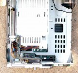
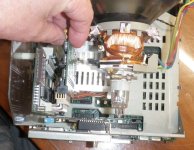
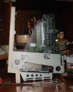
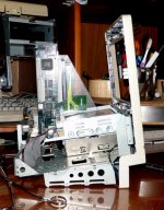
OK, now that I appear to have chased everyone off, I'll close out my contributions with a few pics:

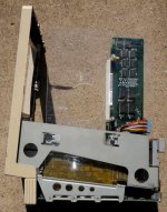
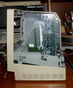
BGE-Side-View.jpg

Side view of the real deal, minus the adapter card of course.

BGE-oblique-Overlap.jpg

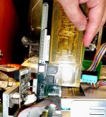
Semi-oblique shot showing the Pivot card overlapping the NIC and its FPU socket.

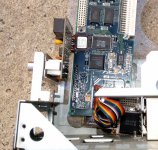
BGE-HeaderSlot-DA15.jpg

This one shows a couple of interesting details:

In the red box at the bottom you see a DA-15 gender changer bolted up to the Asante NIC's backplane plate. These NICs appear to speak AUI natively, having a simple, detachable passthru board with the Lockdown DA-15 connector for a ThickNet Transceiver. The balance of the breakout board is a 10baseT/ThinNet Transceiver setup. Just remove the ThickNet daughtercard/connector assy and there's your DA-15 Video Port's cutout all ready to go. Plenty of room for a homebrew cable and lets face it, they're pretty much ALL going to be custom made cables. My buddy has buckets and buckets of Pivot Cards and no cables for them.

In the red box above you can just make out the 2x40 pin header I have plugged into the NIC's passthru. Had I done a better job of photographing it, you'd be able to see the silvered pins to be soldered to the adapter board. There'll be a little (very little) airspace between the adapter PCB and the drive assembly. Electrical tape time.

Anyway, there you have it, playtime here's over and I'm back to a couple of other projects.  [:)] ]'>

edit: well, that didn't last very long! Looks like if I plugged a second RA wire wrap socket into the passthru of the Pivot Card, I could plug in the one and only SE/30/IIsi NIC in my collection that lacks a Passthru slot.  [}:)] ]'> 

 
Last edited by a moderator:

Trash80toHP_Mini

NIGHT STALKER
BadGoldEagle asked me specifically how we might use a passthru deprived NIC with the baseline card. Couldn't find a socket, so a male RA wire wrap header will have to work as a stand in:

BonusPDSpassthru.JPG

Voila! Instant PDS Passthru for the adapter he originally drew up and tested.

edit: that's a better shot of the DA-15 gender changer's position.

Also wanna suggest that the baseline version of the adapter should also use the wire wrap connector offset trick if possible. That's the only way I can see to retain the ability to bolt the adapter card up to the rear mounting point for stability.

Time to tear this down and put it away so I can stop obsessing over it. Yathink? ::)

 
Last edited by a moderator:

BadGoldEagle

Well-known member
The NIC version of the adaptor looks great.

But I'm afraid a wire wrap makeshift adapter to the adapter might complicate things a little for the SE/30's PDS...

I think I'll make two versions of the card available to download. I found a nice brand new in the box Asante Mini EN/SC for 40 bucks (no photos but it's from a computer supplier, the never take pictures of the items they have in stock), I think I'll get it.

With two versions at their disposal, people will get exactly what they need. Some companies can manufacture one PCB at a time (yes, it'd be cheaper to have a lot of them made but I don't plan on creating a store), and since I DON'T plan on selling the design (KiCad files) the cost of making one card should still be very reasonable.

There are other ways of connecting an SE/30 to the net, so if people can't get the Asante NIC, at least they have other alternatives.

Once I get Themk's files, I'll start working on it!
Thank you for taking the time to design the layout of the NIC version in illustrator, I didn't have the exact dimensions of the Asante NIC, now I do!


Trash80toHP_Mini

NIGHT STALKER
Dimensions aren't exact, I used life size scans of the cards as templates to rough them in for illustrative purposes. But they're darn close.

No problem running the wire wrap connector adapter on the adapter. That's how I'll be installing my Asante NIC. You should check out some of the contraptions on the SE/30 PDS Slot Multiple Upgrades page on gamba!

After I came up with the BonusPDS last night I had another attack of Keep It Simple Stoopid! Just one layout and angled edge so a pair can be nested to shave the height of the combined PCBs significantly.

Made up a prototype, took a little over an hour because I had to search for a few tools in the corner shop in the living room. It took more time to document it than to make it. I left the masking on one side of the plex so it would show up better in the pics.

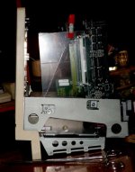
SideView.jpg

SkinnyDayStarTraces.jpg

Check out how skinny the trace section of the LCIII Powercache adapter is, that panel's not even 2.5cm wide! I used that section of one I'd hacked up for parts. It made positioning the standoff holes for the wire wrap connector offset on the board a breeze. The Pivot Card is also bolted up to the adapter with standoffs. Plenty of support for hanging a NIC off the passthru with another RA wire wrap connector.

QuantumMechanics.jpg

Made a worst possible case scenario for mounting my Asante NIC off the BonusPassthru. There should be clearance even for that full height 40MB Quantum monster! I raised the connectors on the prototype about a millimeter, but there's plenty of room to raise the connector assembly a couple more millimeters.

ScootchRoom.jpg

Tried to show it with the VisiblePlus bucket, but didn't work out very well in the shot. SE/30 bucket's really thin by comparison. I'll remeasure the clearance with my pack of post-It note thickness gauge. [:)] ]'>

NestedBoards.jpg

Here's the snapped off corner aligned to show the 7cm overlap of a pair of nested PCBs. That reduces the effective height of each by 3.5CM, a definite cost savings. I didn't want to snap the plexi off any closer to the mounting holes. Between the SkinnyTrace trick and tighter nesting it should bring the cost of a pair of boards down very significantly. Making provisions for scoring and snapping the PCBs in no problem. same for the hacksaw cut slot and snap line for removing the lower rear corner of the PCB.

No AI-games for today, real world prototyping is the bombe. I'll scan in the PCB prototype and tweak that in Illustrator a bit. Hopefully all my scored witness lines will show up along with the holes and outline of the plexi.

Themk's model of the "Minimum Size SE/30 Expansion Card" is your jumping off point. All you need to do is position the the wire wrap connector, its standoff/mounting holes and the matching standoff provisions for the Pivot's connector. It's important to use the wire wrap standoff to retain the holes for chassis mounting the adapter. With the right standoffs, the wire wrap pins of the passthru connector will be at a level similar to a standard soldertail part!

Have at it!

edit: forgot to mention that you can run almost all your connections up the "backside" of the card so you might not need much SkinnyTrace trickery at all. [;)] ]'>

 
Last edited by a moderator:

Trash80toHP_Mini

NIGHT STALKER
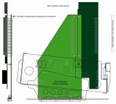
I love my weekday weekends! Just had a great nap and decided a diagram would probably show the new configuration more clearly:

BGE-PivotRiser-Unified-000.jpg

Realized the scaling has been off some all along, but it's the real deal I've been playing with in plexi that matters.

BGE-PivotRiser-Unified-000.PDF


Attachments

  • BGE-PivotRiser-Unified-000.PDF
    101.5 KB · Views: 39

BadGoldEagle

Well-known member
Now that's what I'm talking about! :p   This is a lot better than my original design! Are you sure though that the PDS slot in the chassis is aligned with the mounting ears? Mine are a bit bent so I can't really tell anymore... 

So, here's how the layout should be?

First layer (surface): Some traces

2nd layer: Power

3rd layer: Ground

4th layer (surface): some other traces

I think it's a good idea too to have two layers to route the data traces, that will make things a lot easier.


Trash80toHP_Mini

NIGHT STALKER
Thank you! I take things wayaayaay over the top for fun, just to see if I could do something crazy. Editing down to the practical level of what should be done is gratifying and fun as well.

Layout plan sounds goodto me, but back check it with the PCB design gurus:

-You can also route a few problematic traces on the power and ground planes per DayStar and DiiMO adapters.

-You can run your traces across a narrow space per DayStar LCIII example in pics, but don't.

-Make effective use of the unprecedented luxury of being able to route traces up both sides of the connector.

Concerns, questions for the gurus:

-You've got lots of room on your board, but traces even longer than on the DayStar LCIII adapter.

-This makes me think crosstalk might become an issue. I'll post pics of both sides of the complete LCIII adapter.

-Criss-cross your vertical and horizontal buses (stair-stepping?) just a bit more than necessary?

-You've got lots of area available to do alternating ground lines, could be useful?

Meandering trace lengths probably doesn't matter, but do it anyway?

Don't go by the placement of board edges and hole placement in my PDF files. Work from Apple's engineering diagrams in Designing Cards and Drivers for the Macintosh Family.

/monthly_06_2017/post-902-0-51832900-1496290859.jpg">View attachment 12984

Themk's KiCad workup of the reference card is almost certainly good enough to use. But I'll take this opportunity to ask for someone experienced in doing mechanical drawing takeoffs and inputting them into a high end CAD package to do the community the favor of doing so. I'm a traditionalist, Apple  released these specs, lets use them in a traditional manner and import traditional CAD files into KiCad/whatever. PCB design tools may be good enough for this, but this is a retro-tech community, so let's do it the way they did in the day! [:)] ]'>

When I scan my plexi mockup and mark it up in Illustrator, we'll use that to refine connector placement for the Pivot. Offset of holes for the Pivot card connector's standoffs will undoubtedly be available in EudoDIN connector manufacturer's data sheets. The spatial relationship of mating connectors will be also be defined in the xxxxxxxx standard.

Time to refill the coffee mug, I hope this makes some sense. :blink:


Trash80toHP_Mini

NIGHT STALKER
/monthly_06_2017/post-902-0-28636000-1496290882.jpg">View attachment 12986

This drawing is annoying to me, it "looks" backwards. Apple's convention is to show the boards from the component side. Maybe that's a standard convention? Dunno, I find it's a lot more convenient to work from the solder side as you did in your mockup. That's the side you can actually see in a compact Mac, X-Ray vision required to see through the A/B, PSU and drive cages. I can visualize it well enough, but why the heck should I bother? Besides, I'm usually reverse engineering boards and the solder side is where you can see all the unobscured traces. : :)

That's not really a fair criticism of Apple. They have the necessary diagrams showing the maximum height of components on the various parcels of PCB real estate, so the convention makes a lot of sense in the real world.

Anyway, back on the banana ranch:

My mock-up has a vestigeal chassis clearing notch and a bit of the extra area of the insanely enlarged plexi protocard I used for the template. Pretty sure your adapter won't need to exceed the width of the baseline card.

Ignore everything above the the mounting points in Apple's engineering drawings. Your adapter is a Genoa jib rising a good 8cm above Apple's design limit. It's overlapping your gaff rigged Pivot mainsail that approaches the upper limits of the SE/30's bucket.

I'm really liking the naughty nautical metaphor. Leaving the top of the jib unclipped would look way cool! Drat the luck, its halyard would pierce the top of the bucket like a Rube Goldberg'd Micron Xceed. :-/

se30_3cards.gif

BTW, this pic finally makes the angled passthru of the DiiMO PowerCache adapter. I knew the IIci slot was angled to clear the drive cage. The Passthru's tight proximity to that connector now makes a world of sense.

My HeaderHack for connecting to the Asante NIC might prove useful after all. I should take a whack using that approach for designing an adapter interface card to bring the top of a Rube'd Xceed inside the limits of the bucket.

030ecgs_stack.gif.5330035a06fc5852cd3b4e2f94877a3d.gif


Yet another windmill to add to the list. [}:)] ]'>

 
Last edited by a moderator:

Trash80toHP_Mini

NIGHT STALKER
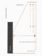
Here's the cleaned up scan of the PlexiProtoSlab I promised.

GenoaJib-001-2p.jpg

No PDF yet, I'll be deciphering Apple's MinimumCard spec. to get the proper dimensions and hole positions nailed down for fabricating a proper Jib. When that's finished and the PDF is uploaded, you can easily make one up for your own testing of the concept. Anyone can print it out, rubber cement* it to cardboard or plexi and make their own mockup for test fitting before ordering their board and parts. Snapping and drilling a clear plexi reproduction should be easy enough.

Plexi paytime's not over quite yet, toledogeek just signed up and threw down an 8 inch gauntlet! [:D] ]'>

*Sprayment preferred, but it's a lot more expensive, tape would fine. Drill first, start your scoring with a sharp utility knife and score the plexi really deep after pre-drilling. I'll test the process.


DatMac

Active member
has this card ever been made? I managed to get couple brand new in static bags of these cards and would love to have one of these risers. I also need a pinout for the video port since my cards didnt come with cables
 
Top