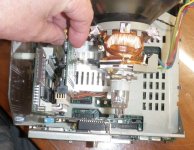
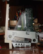
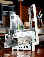
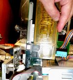
Thank you! I take things wayaayaay over the top for fun, just to see if I
could do something crazy. Editing down to the practical level of what
should be done is gratifying and fun as well.
Layout plan sounds goodto me, but back check it with the PCB design gurus:
-You can also route a few problematic traces on the power and ground planes per DayStar and DiiMO adapters.
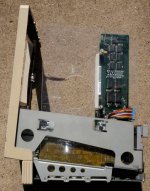
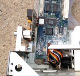
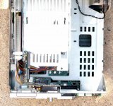
-You can run your traces across a narrow space per DayStar LCIII example in pics, but don't.
-Make effective use of the unprecedented luxury of being able to route traces up
both sides of the connector.
Concerns, questions for the gurus:
-You've got lots of room on your board, but traces even longer than on the DayStar LCIII adapter.
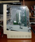
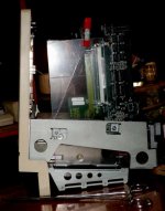
-This makes me think crosstalk might become an issue. I'll post pics of both sides of the complete LCIII adapter.
-Criss-cross your vertical and horizontal buses (stair-stepping?) just a bit more than necessary?
-You've got lots of area available to do alternating ground lines, could be useful?
Meandering trace lengths probably doesn't matter, but do it anyway?
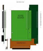
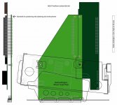
Don't go by the placement of board edges and hole placement in my PDF files. Work from Apple's engineering diagrams in
Designing Cards and Drivers for the Macintosh Family.
/monthly_06_2017/post-902-0-51832900-1496290859.jpg">
View attachment 12984
Themk's KiCad workup of the reference card is almost certainly good enough to use. But I'll take this opportunity to ask for someone experienced in doing mechanical drawing takeoffs and inputting them into a high end CAD package to do the community the favor of doing so. I'm a traditionalist, Apple released these specs, lets use them in a traditional manner and import traditional CAD files into KiCad/whatever. PCB design tools may be good enough for this, but this is a retro-tech community, so let's do it the way they did in the day! [

] ]'>
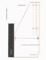
When I scan my plexi mockup and mark it up in Illustrator, we'll use that to refine connector placement for the Pivot. Offset of holes for the Pivot card connector's standoffs will undoubtedly be available in EudoDIN connector manufacturer's data sheets. The spatial relationship of mating connectors will be also be defined in the xxxxxxxx standard.
Time to refill the coffee mug, I hope this makes some sense. :blink:


]
