-
Updated 2023-07-12: Hello, Guest! Welcome back, and be sure to check out this follow-up post about our outage a week or so ago.
You are using an out of date browser. It may not display this or other websites correctly.
You should upgrade or use an alternative browser.
You should upgrade or use an alternative browser.
Macintosh SE/30 Restoration
- Thread starter PotatoFi
- Start date
techknight
Well-known member
Unless the ASC chip itself is bad, you need to check every single pin on that ASC Chip back to its origin points and look for breaks. Thats ALL control lines, address lines, select lines, etc...
If it all checks out, its likely a bad IC.
If it all checks out, its likely a bad IC.
Last edited by a moderator:
PotatoFi
Well-known member
I've checked all of the lines from the ASC chip back to various places like the GLUE, FPU, and PDS. No problems found. I guess I'd better start hunting for a donor board?Unless the ASC chip itself is bad, you need to check every single pin on that ASC Chip back to its origin points and look for breaks. Thats ALL control lines, address lines, select lines, etc...
If it all checks out, its likely a bad IC.
Thanks! Yes, I plan to make the STL's available.I like your SCSI2SD mount. Would you be willing to share the STL?
techknight
Well-known member
if all the lines check out, then it is likely a bad IC. Youll probably need to locate a donor board that uses the same apple sound chip, its probably easier to get your hands on a board that has a blown up battery or something and use that for parts.
PotatoFi
Well-known member
The search is on.if all the lines check out, then it is likely a bad IC. Youll probably need to locate a donor board that uses the same apple sound chip, its probably easier to get your hands on a board that has a blown up battery or something and use that for parts.
---
A few more developments! My wife bought me a Mac ROM-inator II! I wasn't happy with the paperclip or rubber band solutions, so after a handful of little prototypes, I came up with this!
I also went ahead and boosted it to 128mb of RAM. Yes... it's silly. But it's done. Next, I'll be installing System 7.5.5 on it, and installing my Ethernet card. Until I can find a donor board to harvest an ASC from, that issue is going to have to go on the backburner.
PotatoFi
Well-known member
Great news! Despite his screen name, @EvilCapitalist has sent me a parts SE/30 board to scavenge an ASC from. Thank you very much, @EvilCapitalist!
Let's have a look at the damage.
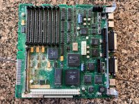
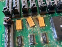
Yep, Maxell bomb. How about the ASC? That's what we're after here. A bit of corrosion was present, but it looked salvageable to me.
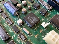
I decided to scrub down the whole board with some vinegar to try to stabilize things a bit. I was a bit too vigorous with the toothbrush though, and knocked an IC right off the board. I think this is a RAM muxer?
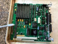
After a rinse under tap water, and hitting it with the air compressor, it was time to desolder the ASC. I don't have a hot air station, so we'll have to use another method.
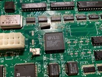
First, a generous amount of paste flux. There's a lot of corrosion to burn through.
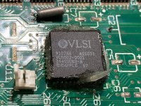
Next, I heated up the pins with the iron, and fed in a generous amount of desoldering alloy. A brand name of this stuff is Chip Quik. It's basically solder, except the melting point is super super low, so it stays molten for a very long time. Here, you can see it in a molten state, even though I've put down the iron and grabbed my phone to take a photo!
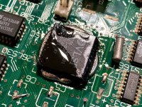
One lesson I did learn with this: you need to get the pins nice and warm before adding the desoldering alloy. If you don't, the alloy will just follow your iron around instead of sticking to the pins.
After coating each side in desoldering alloy, I began raking my iron back and forth across all sides. I kept the iron moving pretty quick, rake-rake switch. Rake-rake switch. Rake-rake switch. After a few passes... pop! Suddenly, the IC moved off of the pads and was free to pick up with some tweezers!
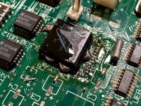
I used the iron to reheat the pins on the chip (super fast and easy) and the solder sucker to remove the excess from the pins. A quick scrub down in some Isopropyl alcohol:
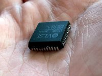
The board looks pretty good too! Here's what it looked like. After this is cleaned things up with some desoldering braid. Not that this board will ever work again... but it's great for practice. You may have noticed that I removed the caps earlier - I will certainly keep it around for parts, or for a reference board, so I wanted it to be stable for storage.
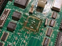
Hopefully tomorrow, I will desolder the ASC from the good board, and solder down this new ASC. I sure hope it works!
Let's have a look at the damage.

Yep, Maxell bomb. How about the ASC? That's what we're after here. A bit of corrosion was present, but it looked salvageable to me.

I decided to scrub down the whole board with some vinegar to try to stabilize things a bit. I was a bit too vigorous with the toothbrush though, and knocked an IC right off the board. I think this is a RAM muxer?


After a rinse under tap water, and hitting it with the air compressor, it was time to desolder the ASC. I don't have a hot air station, so we'll have to use another method.

First, a generous amount of paste flux. There's a lot of corrosion to burn through.

Next, I heated up the pins with the iron, and fed in a generous amount of desoldering alloy. A brand name of this stuff is Chip Quik. It's basically solder, except the melting point is super super low, so it stays molten for a very long time. Here, you can see it in a molten state, even though I've put down the iron and grabbed my phone to take a photo!

One lesson I did learn with this: you need to get the pins nice and warm before adding the desoldering alloy. If you don't, the alloy will just follow your iron around instead of sticking to the pins.
After coating each side in desoldering alloy, I began raking my iron back and forth across all sides. I kept the iron moving pretty quick, rake-rake switch. Rake-rake switch. Rake-rake switch. After a few passes... pop! Suddenly, the IC moved off of the pads and was free to pick up with some tweezers!

I used the iron to reheat the pins on the chip (super fast and easy) and the solder sucker to remove the excess from the pins. A quick scrub down in some Isopropyl alcohol:

The board looks pretty good too! Here's what it looked like. After this is cleaned things up with some desoldering braid. Not that this board will ever work again... but it's great for practice. You may have noticed that I removed the caps earlier - I will certainly keep it around for parts, or for a reference board, so I wanted it to be stable for storage.

Hopefully tomorrow, I will desolder the ASC from the good board, and solder down this new ASC. I sure hope it works!
techknight
Well-known member
Yea, that takes some dedication. I would have hot-air gunned it.
PotatoFi
Well-known member
Me either, ha!Pretty remarkable that you did that without a hot air gun. I sure wouldn't have wanted to do that.
Yeah, I would have too if I had a hot air station!Yea, that takes some dedication. I would have hot-air gunned it.
Impressive. The one thing I was amazed at was after taking the plunge, just how easy it is to work with hot air. I won’t fear it again. That being said, your effort was tremendous!
Thanks! This project almost convinced me to look into a hot air station... but I decided that I could get it done with just an iron. Or could I? Read on...
First, I decided to clean up the "junk" board for some practice. It will be great to keep around both for parts, and for reference.
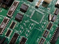
Next, on the good board, I went crazy with the flux paste.
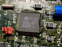
I gotta admit that this part took awhile, and was a bit scary. I had a hard time getting the desoldering alloy to evenly coat each side of the chip. At this point, I was pretty convinced that I had permanently destroyed my SE/30. Why did I mess with it? Would not having sound been that bad?! What was I thinking?!
Eventually I removed it all and started from a clean slate, and the IC popped off a lot faster.
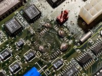
Here's the supposedly bad ASC, removed.
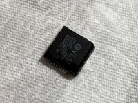
Next, I cleaned up the pads. I thought a couple of them were gone, but I scraped away at them for awhile and sure enough, there were pads! That could explain why the first ASC failed. I am pretty sure that there was continuity... pretty sure. I'll keep the old ASC around. Maybe it's still okay.
Next, I tinned a couple of pads. In this photo I have only tinned one; I ended up removing that and tinning a couple of pads on another side that was easier to get to.
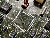
I ran the iron over each of the pins to make sure it was clean.
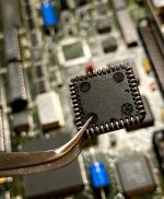
Next I set the IC in place, and flowed the two tinned pads. The IC settled down on the pads. Next I soldered a pin on the opposite corner, and double-checked that everything was straight. Then, I hit all of the pins with liquid flux, and started soldering the rest of the pins. I thought I could drag-solder everything, but I really struggled with bridges so eventually I just soldered every pin, one at a time. At this point, I was REALLY convinced that my SE/30 was dead for good. Totally hosed.
After cleaning it with alcohol and hitting it with the air compressor, here's what it looked like:
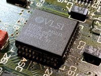
I reassembled it, flipped the power switch, and...
I am doubting the fix a bit - I booted from the ROM and fired up Sim City from a floppy disk. The sounds all work just fine but are pretty bad quality. I think that's just because they're just low-quality samples. Curiously my Bolo or Microsoft Flight Simulator sounds didn't work. I'll get System 7.5.5 booting next, and play some more sounds to confirm, but I am 90 percent sure that the sound issue is fixed.
Thanks for identifying the problem, @techknight!
techknight
Well-known member
Ok, now that I can see the board with the chip removed, I am spotting a few potential trouble spots for breaks. Where the outer pad is no longer connected to the inner pad and could have been the source of your problems. When soldering in the new chip, you added fresh solder from the tip of the pad and it flowed inward, bridging the breaks. (potentially).
Here is a diagram explaining what I mean: I marked in read the trouble areas, and marked in green the breaks
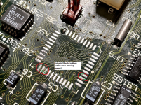
Here is a diagram explaining what I mean: I marked in read the trouble areas, and marked in green the breaks

Similar threads
- Replies
- 10
- Views
- 750
- Replies
- 2
- Views
- 327
- Replies
- 3
- Views
- 406
