• Updated 2023-07-12: Hello, Guest! Welcome back, and be sure to check out this follow-up post about our outage a week or so ago.

Macintosh SE/30 Restoration

PotatoFi

Well-known member
I planned to do a restoration thread like I usually do... but sadly, this one got off to a very rough start. If you have SMD recapping and pad repair, I could really use some advice! Read on...

---

I was in Portland, OR a couple of months ago to teach a class, and decided to check Craigslist for Macs while I was there. I found an ad for an SE/30 for $100 with no images and almost no description: "untested, for parts". I emailed the seller and asked for more information, but he wasn't really willing to say anything more about it, other than "it's untested, that is why it is so cheap". Based on that, I asked to come look at it, but kept my expectations in check... this one screamed "blown up PRAM battery".

When I arrived, I found that the seller was very much into vintage computing, but claimed that he just hadn't tested the machine. He was willing to pop the back cover off to check and remove the PRAM battery which I very much appreciated, so I gave him asking price for his machine. He did mention that he has a YouTube channel, which I went and found.

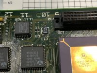
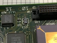
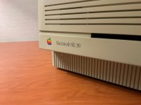
Here's where he received the SE/30. It looks like it had a Micron Xceed videocard with it, which he sadly did not include with the Mac. I'm not sure why it wasn't installed in the machine, but it has the bracket that my SE/30 is missing. Here's a photo of it that I snapped in my hotel room that evening:
IMG_0008.jpg

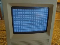
A few days later, I got it home and did a power-on test, here are the results.
IMG_20191102_182005.jpg 

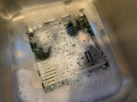
There was actually a floppy icon blinking back there, but it definitely would not boot up. I knew the caps were probably a mess, so I shut it back down, removed the logic board, and gave it a good scrub with soap, water, and a toothbrush. I chased the water out with alcohol, and left it to dry.
IMG_0026.jpg

After letting it dry and trying again, I got a different pattern on the screen.
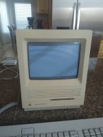
IMG_20191103_085057.jpg

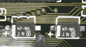
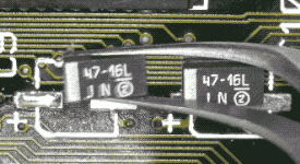
At this point, I took the obvious next step, and ordered new tantalum capacitors for the board. A friend of mine had sent me another SE/30 board to recap, so I ordered two sets of components. At this point in time, I'd already successfully recapped both an SE/30 and a Classic II for him, and now had a second SE/30 logic board to recap for him. The parts arrived, and I knocked the whole thing out in about 30 minutes. Here's one of the caps from that job. I was (key word, was) feeling VERY confident about my recapping skills at this point!
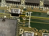
IMG_0195-1.jpg

Tonight, it was finally time to recap my own SE/30 and see if it would boot! Curiously, I noticed that one of the old caps on the board was kinda crooked:
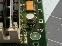
IMG_0201.jpg

Note the mess around these capacitors. This is a bit worrisome... but the traces look okay everywhere, so we should be good, right?
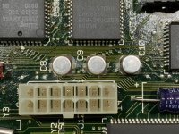
IMG_0202.jpg

I got to work, desoldering the old capacitors. Here's my usual process (more details about how I do it are available here):

1. Clean around the capacitor with cotton swabs and alcohol, scrubbing as much corrosion as possible from the pads

2. Hit each pad with a flux rework pen

3. Grasp the capacitor with tweezers, and heat one pad, while very gently rocking the capacitor up and away from that pad

4. Switch to the other side and do the same, going back and forth until the cap eventually is disconnected from both pads and can be lifted away.

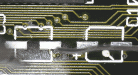
But, luck was not on my side... I just couldn't get the pad to flow, no matter what I did. And then, disaster struck:
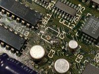
IMG_0203.jpg

WHOA, okay, okay. Only one pad lifted and there's still continuity... I can fix this! Let's just move to another one and come back to this later...
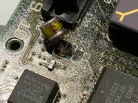
IMG_0205.jpg

HECK'N. LIKE SERIOUS HECK HERE. I MEAN HEEEEEEEECK.
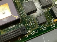
IMG_0206.jpg

And... that's where I'm at on it tonight. Four successful, almost completely uneventful logic board recaps... and then this. I very carefully tried a couple of other capacitors (there are 8 left on the board), but I just could not get anything to flow, no matter what I tried. So I stopped before causing any more damage.

So... I need advice:

  1.  How can I repair the two pads at C13? One pad is totally gone, and the other is barely hanging on.


    Where can I buy copper to cut a new pad?
  2. What kind of epoxy do I need to stick them back down, and where do I get it?

[*]How do I desolder the rest of the caps without causing more damage? My usual tricks just aren't working here.

[*]If I need to run wires, what kind should I use and where do I get it?


I have a typical soldering station at my disposal, I little Hakko FX-888D. If you have any advice for me... I'd love to hear it.

 
Last edited by a moderator:

AwkwardPotato

Well-known member
If you really want to repair the pads for C13 or any of the other capacitors, I suppose you could find a sheet of copper foil (without adhesive, can be found on Amazon), cut new pads from it, and attach them to the board with a high-temperature-resistant epoxy (I know such a thing exists but I can't seem to find it atm). The way I've dealt with this in the past, albeit far less professional, was to cut off the barely remaining pads, solder a jumper wire to each of the pads on the bottom of the capacitor, hot-glue it in place, and then solder the jumper wires where necessary.

If it were me, I would stop rocking the caps and heating each side with the soldering iron. This board appears to be in very rough shape, so I'd recommend that you use as little heat as possible to remove the caps. It would be a better idea to wiggle each one off with a pair of pliers veeery slowly. Start rocking it only slightly, perpendicular to the leads. After a while you'll feel it loosen up and eventually the leads will break off above the plastic base. The remaining leads can then be desoldered and the pads can be wicked clean.

Kynar wire-wrap wire (28-30AWG, can also be found on Amazon) works very well for jumper wire.


Bolle

Well-known member
That’s why I always go for the twist method when removing caps. The excessive heat you have to put into the pads to actually get this corroded old solder to flow does more harm than good.

A quick little twist will just have the legs break inside the cap and not put any strains on the pads. Always push down onto the cap while twisting it left and right, never pull up.

The heat-pull-heat thing you did actually is the worst thing you can do. When heating and lifting one side you leverage the other side off the board.

I would recommend everyone tries to twist off some caps on a junk board to practice. You will never go back to do anything else. I seriously did not break a single pad yet using that method but did rip a off a lot of them when going at heating them one side at a time while carefully lifting.

This is how it looks with the caps twisted off properly. Cleaning the pads is easy afterwards:

960C4B5A-CACD-402D-95A6-3C73A5871F4E.jpeg

Also you can clearly see the rest of the legs of the caps still sitting there.


Bolle

Well-known member
Cold. Just grab some pliers and gently twist it off.

As said pushing down on the cap is the key here. You don’t want any upwards force pulling on the pads.

That way the cap always breaks before the pad does. Even works with new caps that haven’t started to rot inside, so the pads can take quite a beating as long as you don’t pull up.

Also never pull upwards. Ever. :tongue:


Byrd

Well-known member
Thanks Bolle - I’ll try this method on some pending 2 x SE/30 board repairs. The old chop off vs. desolder method is proving less reliable as the boards age.


PotatoFi

Well-known member
Up until now, I thought that the twisting method was lazy and dangerous... but I was clearly wrong. I tried it on all 8 remaining caps, and it worked beautifully. Half the time, the cap would come clean off the board, leaving the legs attached to the pad. The other half of the time, the legs would pull out of the capacitor, leaving the plastic base on the logic board. I'd snip off the legs with flush cutters, and remove the base.

IMG_0213.jpg

After removing the capacitor, here are three different stages of pad preparation: cleaned an ready for a new capacitor, only cleaned with alcohol, and not cleaned at all.

IMG_0211.jpg

After removing the cap, the first thing I did was swab everything with isopropyl alcohol, being careful to not tug at the pad. Next, I'd liberally coat the two pads with flux paste.

IMG_0214.jpg

Next, I heated up each pad with the iron. The combination of heat and and flux seemed to quickly burn through the awful junk on the pad, and dislodge the leftover pins from the capacitor. Here you can see that only the pad on the left is done, but the old pin has floated away.

IMG_0215.jpg

Next, I dragged some desoldering braid across the pad with the iron on top. The desoldering wick seems to have a very lightly abrasive action on the pad, which cleans them up nicely and removes any old solder. Each pad got a couple of quick passes with the desoldering wick, maybe a bit more if they were really nasty.

 IMG_0216.jpg

Finally, and fast-forwarding to all three of these being done, I clean everything with isopropyl alcohol and cotton swabs.

IMG_0217.jpg

Everything else all cleaned up. Here you can see one of the pads that I lifted when I was attempting to desolder the old caps.

IMG_0219.jpg

Okay, time to solder! I find SMD stuff to be very easy, once you know "the trick". I always start by tinning just one of the pads.

Small Step 1 - Tin Pads.gif

Next, bring my parts to the board.

Small Step 2 - Get Parts.gif

Next, I heat the tinned pad, and slide the part into place. When I have it where I want it, I remove the heat before letting go with my tweezers.

Small Step 3 - Solder.gif

Finally, after double-checking that polarity is correct, I go back and solder down the other side.

Small Step 4 - Solder Other Side.gif

After soldering everything in, I needed to deal with the mess I'd made at C13. One of the pads was completely gone, and the other pad was moving around, but was still connected when I tested it with a multimeter. I decided to tack the capacitor down to the floating pad, and then use a small piece of solid wire to connect the positive terminal to the nearby via. Here's the wire:

IMG_0222.jpg

And here's what it looked like, after solder. It's messy, but there's continuity where there needs to be. I added a dab of hot glue to keep it in place. C13 is a +5v supply filter, so if things don't work, or stop working, I'll know where to go first. And I'll be ordering some wire to have it for next time, or to rework this.

IMG_0223.jpg

Once I was done soldering everything, I washed the board down with alcohol and scrubbed around the capacitors with a toothbrush to remove any leftover flux. Here's the completed board:

IMG_0225.jpg

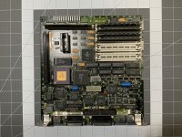
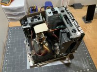
And it's installed in the computer, but I think I'll wait until tomorrow morning to try powering it on. It's had most of the afternoon and the whole evening to dry, but better safe than sorry. I just noticed that the machine is missing the hard drive caddy, expansion slot bracket, and SCSI ribbon cable. I'll need to track those three things down.

IMG_0226.jpg

Plans going forward:

  • Test for power-on and boot up from floppy
  • Tear down
  • Inspect analog board, recap as needed
  • Clean and lubricate floppy drive
  • Clean everything
  • Retrobrite case
  • Source hard drive caddy, SCSI cable, and expansion bracket
  • Install SCSI2SD
  • Install more RAM (either 64mb or 128mb)
 
Last edited by a moderator:

superjer2000

Well-known member
That’s why I always go for the twist method when removing caps. The excessive heat you have to put into the pads to actually get this corroded old solder to flow does more harm than good.

A quick little twist will just have the legs break inside the cap and not put any strains on the pads. Always push down onto the cap while twisting it left and right, never pull up.

The heat-pull-heat thing you did actually is the worst thing you can do. When heating and lifting one side you leverage the other side off the board.

I would recommend everyone tries to twist off some caps on a junk board to practice. You will never go back to do anything else. I seriously did not break a single pad yet using that method but did rip a off a lot of them when going at heating them one side at a time while carefully lifting.

This is how it looks with the caps twisted off properly. Cleaning the pads is easy afterwards:

Also you can clearly see the rest of the legs of the caps still sitting there.
This is the best method to use and what I do exclusively to remove capacitors.  I had restored two SE/30s a few years ago when I naively thought that desoldering was the best way to remove caps and probably pulled 4 traces between the two systems.  I just restored a third SE/30 with this method and pulled all the caps off in about 5 minutes with no lifted pads.  As noted, you push down gently while twisting the caps in both directions with very small movements.  This doesn't apply any upwards force on the pads (which is where they are weakest).


LaPorta

Well-known member
Excellent, excellent work! I love the tiny movies; they are great for those starting out. I wish I had the time to do all that documenting, your efforts do the forum a great service.

One thing that I do that differs a little on what components you are using. If you are instead using organic polymer caps to duplicate the OEM look (as I do), there sometimes is so little lead sticking out that it is difficult to solder from the side once the component is in place. I will use very little solder to tin both pads at the start, and then hold the component down over in place where I want it. I then do similarly as  you do on the first side, but apply some downward pressure so that the component "sinks" into the thin solder layer. I then heat the other side doing the same so that side sinks as well. If it appears lopsided, just heat back and forth until it is snug to the surface. This also saves you from needing the "third hand" for solder in case things move a bit while you are applying it.


james_w

Well-known member
@PotatoFi beautiful documentation. That’s exactly how it should be done by the book.

This should be made sticky or something.
I second this! Very useful and clear documentation of your method. Pretty much exactly the same as mine, but admittedly more rigourous.

Also I just want to mention that I use the twist method used by @Bolle too and also want to make it very clear how important it is to press down on the caps whilst doing so. I've recapped around 20-30 boards in the last 4 years or so using this method. I think I've lifted about 3 pads in that entire time.

 
Last edited by a moderator:
PotatoFi

Well-known member
Thank you everyone for the compliments! Much appreciated. I enjoy these restoration logs quite a bit, it's a fun chance to "hang out" with people who like the same stuff that I do, and hopefully encourage others to dig into similar projects.

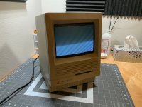
On to today's update! This morning, I plugged the machine in. On the display, I got this:

IMG_0227.jpg

On the audio spectrum, something very significant happened. Instead of trying to explain it' I'll just show a video.


View attachment IMG_0228lq.mp4


I'm really at a loss about how to describe that. I've seen the term "Chime of Death" a lot, maybe this is it? I'm not sure. It doesn't seem like a ROM issue to me, because if you remember, I could see a floppy disk "?" when I did my initial power-on, and this sounds a like like a "chime" to me, which I think comes from the ROM.

I decided to investigate the most obvious problem first: DNS. It's always DNS, right? Well, it didn't end up being DNS, so I investigated the next most obvious thing: RAM. First, I reseated the RAM. No change.

IMG_0229.jpg

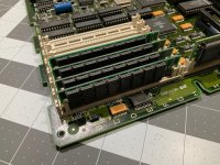
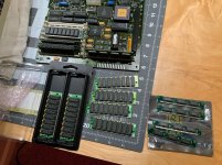
Next, I dug into my box of spare parts to try some different RAM, and was very surprised at what I had laying around. The most interesting was the 8-chip sticks in the middle; they were in a plastic bag labeled "SE/30", which reminded me that these originally came out of Bank B on this machine. One of the slots is broken (more on that later), so I had removed the RAM immediately and never put it back in. I decided to swap these four sticks out with the RAM that was in Bank A.

IMG_0231.jpg

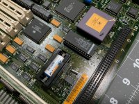
I also discovered a PRAM battery from RetroFixes.com! I ordered one earlier today for this machine... oops. Oh well, always good to have a spare. I went ahead and installed this one, although I did manage to break part of the battery clip.

IMG_0230.jpg

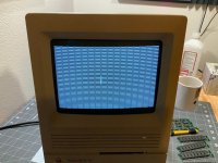
And now for the power-on with the 4 sticks of 8-chip Apple RAM! There's good news, and bad news.

IMG_0233.jpg

The good news is that the machine doesn't make that horrible sound anymore! It also once again shows a blinking "?". The bad news is that it's exhibiting the exact same patterns as before, so a recap didn't fix that. I feel like this is a pretty common issue, but I don't remember the name for it. I did consult the Dead Mac Scrolls, and it doesn't mention this issue, so I have some research to do. I do think that it must have something to do with video generation.


Bolle

Well-known member
Check all address lines to the VRAM address muxes and from their outputs to the VRAM. Also one of the muxes itself might be bad. Start with UD8, it has the most corrosion on its legs.

My bet is that there’s no output from UD8 and the address lines are ok. Otherwise A0 and A1 both had to be broken to produce the image you got.

Worst problem I had so far was an intermittent connection on one of them. It would meter out ok sometimes but not always.

Edit: Maybe I’ll take that bet back. I had a really similar issue on a board just a few days ago. Really fancy looped chime and similar pattern on screen. I was only missing every  other byte though which was a clear pointer that A0 was missing. You might indeed have two lines missing there.

I guess I too many of those boards to remember every fault and seem to start forgetting things...

 
Last edited by a moderator:
PDub53

New member
My first post...just joined.  After 25 years, started up my SE/30 I bought new and carried around the world.  Everything worked great still...except the hard drive.  Had to rely on a floppy emergency disk, but could get the old Iomega Bernoulli Mac Portable and Spin  external hard drive to load.  However, things have gone downhill to the point where the power switch sometimes works, sometimes doesn’t.  Pulled it apart, cleaned out the dust and reassembled and it worked...for two days, then vertical stripes showed up...jailhouse time!!  Acquired a replacement PSU, just in case, and opened the SE/30 up today....Cap C1 just fell off during logic board removal.  So I read this string, and used the cold “pull” method on the rest of the caps.  All off, all pads fine.  You all are great!!!  Thanks for sharing the wisdom.  Time to order new caps, might as well do the analog board as well....


PotatoFi

Well-known member
Acquired a replacement PSU, just in case, and opened the SE/30 up today....Cap C1 just fell off during logic board removal.
might_be_of_service_david_bowie1.gif

I meant to post these earlier. Better late than never!


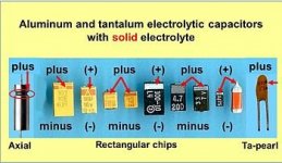
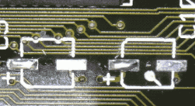
As for what goes where, this post has a great photo reference. I also always have to look up tantalum SMD polarity to make sure I get it right, so here's that:

350px-Polarity-rectangular-chips.jpg


PDub53

New member
Thanks a bunch, PotatoFi....was just getting ready to ask about Cap options.

note....my board is in GREAT shape, except the right plastic connector for the ROM has cracked.  I would think it should be ok, but has anyone else run into that?

F07A41A9-3955-40AD-B8E7-BC23E8B41394.jpeg


captjon320

Active member
PotatoFi, this is wonderful.  I'm new to the community and just finished my first recap of a Mac Classic Logic Board.  It wasn't pretty, but it works!  I wish I would have found this thread before venturing down the recap road.  

Question for all, granted this is a Mac Classic, I don't know if it belongs here.  Like I said, recapped the logic board, cleaned it up and placed it back in the original machine.  I got the "ding", which was missing previously.  However, I was looking a blank screen.  The screen prior to the recapping was a checkerboard pattern.  I happen to have another Classic, which is in working order, so I put the recapped logic board into that machine and it booted right up (made me so happy that I actually fixed it).  Here is the question, I believe that I now need to look at recapping the analog board.  I would appreciate some input before I start tearing into it.

Thanks for having such a great community with wonderful information!


techknight

Well-known member
Check all address lines to the VRAM address muxes and from their outputs to the VRAM. Also one of the muxes itself might be bad. Start with UD8, it has the most corrosion on its legs.

My bet is that there’s no output from UD8 and the address lines are ok. Otherwise A0 and A1 both had to be broken to produce the image you got.

Worst problem I had so far was an intermittent connection on one of them. It would meter out ok sometimes but not always.

Edit: Maybe I’ll take that bet back. I had a really similar issue on a board just a few days ago. Really fancy looped chime and similar pattern on screen. I was only missing every  other byte though which was a clear pointer that A0 was missing. You might indeed have two lines missing there.

I guess I too many of those boards to remember every fault and seem to start forgetting things...


Wow, I am glad I am not the only one that has that problem of remembering all the faults. I havent ran into any of the crazy ones you have, looping chime, etc. 

 
Top