JC8080
Well-known member
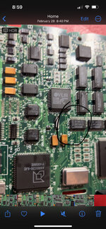
@zezba9000 ,@9166188 , @elemenoh , did any of you ever solve your death chime? I have the same issue with a board I just recapped. I recapped the board and PSU and it worked fine for a day. I had it running and a breaker tripped, I think because of my 13" CRT. When I restarted the machine I have the chime followed by the death chime. I also get the brief grey screen right after I switch it on. It did boot one time but showed display issues on the screen, it has not booted since. I have swapped PSUs with a known-good unit, removed the RAM SIMMs, and re-flowed the onboard RAM chips. The fact it did boot but had display issues makes me suspect the onboard RAM, since the VRAM is shared with the RAM.
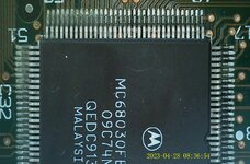
My next step is to swap the RAM chips off another non-working board I have, though unfortunately the condition of those chips is unknown. @imactheknife mentioned in another thread that the onboard RAM/VRAM is often an issue. Swapping the RAM on this board is a bit of a job, so I wanted to check and see if anyone had found a different cause before I jump into the project.
My next step is to swap the RAM chips off another non-working board I have, though unfortunately the condition of those chips is unknown. @imactheknife mentioned in another thread that the onboard RAM/VRAM is often an issue. Swapping the RAM on this board is a bit of a job, so I wanted to check and see if anyone had found a different cause before I jump into the project.


")