• Updated 2023-07-12: Hello, Guest! Welcome back, and be sure to check out this follow-up post about our outage a week or so ago.

Mac-to-VGA monitor adapter struggles

bigmessowires

Well-known member
Here's the Mac's CSYNC signal, compared to the HSYNC and VSYNC signals output by my mcu program. There's some jitter, but the signals are clean and it looks promising:

sync-split.png

Connecting this abomination of wires to my Mac IIci and the VG900b:

IMG_3723.jpg

IT WORKS!!! Oh my God it actually works. VG900b has entered the chat. The white whale has finally been harpooned.
 

Phipli

Well-known member
Here's the Mac's CSYNC signal, compared to the HSYNC and VSYNC signals output by my mcu program. There's some jitter, but the signals are clean and it looks promising:

View attachment 63337

Connecting this abomination of wires to my Mac IIci and the VG900b:

View attachment 63338

IT WORKS!!! Oh my God it actually works. VG900b has entered the chat. The white whale has finally been harpooned.
That, is one picky monitor.

If you press "1" on the buttons, then select auto adjust (using "2"), the shimmer should clean up and the black bar at the right vanish.

Congratulations on getting it running!
 

joshc

Well-known member
Here's the Mac's CSYNC signal, compared to the HSYNC and VSYNC signals output by my mcu program. There's some jitter, but the signals are clean and it looks promising:

View attachment 63337

Connecting this abomination of wires to my Mac IIci and the VG900b:

View attachment 63338

IT WORKS!!! Oh my God it actually works. VG900b has entered the chat. The white whale has finally been harpooned.
That's a good picture, so a nice result in the end.
 

NJRoadfan

Well-known member
Yes that's just what I was thinking. For the IIci and IIsi we've seen that you get both CSYNC and sync on green. Are there any Mac models or video cards that output only sync on green? Anybody have an old NuBus card like a Toby, or Ivi, IIvx, Q700, Q900, LC, LCII and able to test it?
Apple appears to have always provided composite sync on their cards, don't know about 3rd parties. See: https://vintageapple.org/develop/pdf/develop-03_9007_July_1990.pdf (page 81)

and http://www.retrotechnology.com/herbs_stuff/mac_monitor_note.html

Fun fact, it looks like you can configure the 8-24GC card to output 15.75khz RGB video, aka "RS-170a video".
 

bigmessowires

Well-known member
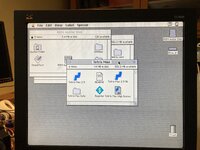
It's been a long couple of weeks fighting with this, so I need to stop and appreciate there's actually an image from the IIci on the VG900b...

But this isn't end: the picture quality is poor, due to the jitter problem described earlier. The photo makes it look better than it is. HSYNC edges are jumping around by +/-5 pixels on each line, so I'm amazed it looks half-way decent.

I tried a new approach. Instead of the microcontroller directly generating HSYNC (with jitter), it generates an enable signal for passing CSYNC through a couple of NAND gates. When enabled, HSYNC = CSYNC. When not enabled, HSYNC = 1. This allows HSYNC falling edges to appear exactly where they should. There is still jitter on the rising edges of HSYNC, but I don't think that should matter.

I tested this, and it looks a lot better, but there's still some annoying shimmer. It's usable but pretty annoying. I'm not sure what causes this, maybe jitter on the rising edge of HSYNC, or jitter on both edges of VSYNC. Or maybe it's 16 MHz switching noise on ground from the microcontroller's clock. Unfortunately it's not quite production-worthy as it stands now.

Apple appears to have always provided composite sync on their cards, don't know about 3rd parties.

OK, that's good news as far as this approach goes.
 

Phipli

Well-known member
I tested this, and it looks a lot better, but there's still some annoying shimmer. It's usable but pretty annoying. I'm not sure what causes this, maybe jitter on the rising edge of HSYNC, or jitter on both edges of VSYNC. Or maybe it's 16 MHz switching noise on ground from the microcontroller's clock. Unfortunately it's not quite production-worthy as it stands now.
Have you run auto adjust on the monitor? It can clear up the image some.

Also, shielding is important with video, is there a chance the prototype is introducing interference? Is the shimmer in the colour, or the timing?
 

bigmessowires

Well-known member
Oops, I've managed to brick my Arduino (an Adafruit ATMEGA32u4 breakout) by setting the clock select fuse to the wrong value. As far as I know that's not recoverable. RIP Arduino. So that's the end of this experiment for now.

Yes I ran the monitor's auto-adjust, and it fixed the image width. The picture looks stable, put there's a pattern of faint diagonal lines moving through the whole image including areas of solid color. I would guess it's probably due to noise from the microcontroller rather than jitter, but I'm not super confident. There aren't too many opportunities for mcu noise to infect the RGB signals here, and there's no directly shared ground between my mcu circuit and the VGA ground, which is where I'd be most suspicious of a problem. The ground path is back through the floppy port, through the IIci logic board, out the video connector to the VGA adapter.

Anyway this seems like a promising path if i can figure out the shimmer. Maybe it'll improve if I tidy everything up into a neat PCB instead of a nest of wires, or maybe it'll be worse because the mcu will be physically much closer to the RGB signal traces. I know there are techniques to help isolate EMI noise in power supplies, like ferrite beads and extra capacitors, but that type of design is definitely not my strength. Maybe there are some hints in the IIci schematic. It has lots of high speed clock signals but still manages to generate noise-free analog voltages for RGB.

If the shimmer/noise is insurmountable, maybe I should go back to the LM1881 + one-shot idea. I'm guessing that would probably work. It might even be possible to do it with two one-shots (one each for HSYNC and VSYNC) and no LM1881... need to think about it more. But that approach is not nearly as flexible as using an mcu.
 

bigmessowires

Well-known member
Wow, I've really been looking at this for way too long, and I need a break. But one final question for now, and an update.

The question: Is this whole sync-splitting business really only relevant for 640 x 480? At 512 x 384 the IIci already outputs separate sync. Are there any video modes for the IIci, IIsi, old NuBus cards, Ivi, IIvx, Q700, Q900, LC, LCII that are higher resolution that 640 x 480 and that only have composite sync? If not, and this is strictly a 640x480 effort, then I can make some simplifying design changes.

The update:
  • The prototype batch of LM1881-based adapters is finished and shipping now. Will they be here in time for a Saturday demo at Mactoberfest???

  • I'm convinced that a 74x123 dual one-shot could generate both HSYNC and CSYNC, and I've purchased parts to test it. But the timing would be fixed by the RC component values, and there wouldn't be any blinkenlights, so this would be a bare-bones solution.

  • Also purchased some ATTINY202 microcontrollers for further testing of the MCU idea. It's an 8-pin device costing 50 cents that's still more powerful than I need... externally clockable hardware timers, configurable custom logic, sleep modes, ADC, USART, I2C, there are a lot of interesting possibilities.
 

jmacz

Well-known member
Oops, I've managed to brick my Arduino (an Adafruit ATMEGA32u4 breakout) by setting the clock select fuse to the wrong value. As far as I know that's not recoverable. RIP Arduino. So that's the end of this experiment for now.

Do the Atmega's support high voltage programming to reset those fuses?
 

dougg3

Well-known member
At 512 x 384 the IIci already outputs separate sync. Are there any video modes for the IIci, IIsi, old NuBus cards, Ivi, IIvx, Q700, Q900, LC, LCII that are higher resolution that 640 x 480 and that only have composite sync? If not, and this is strictly a 640x480 effort, then I can make some simplifying design changes.

Wait, the IIci has a 512x384 mode? The dev note doesn't refer to one. Although the IIsi dev note does (switches 134) -- but it claims it doesn't output vsync and hsync with it. Just composite sync. I feel like people wouldn't go out of their way to use 512x384 with a VGA monitor though, so I'm thinking it's a nonissue either way...

It seems like they started heading more toward VGA-compatible modes pretty quickly. Wouldn't be surprised if 640x480 is the highest one that needs it...

Do the Atmega's support high voltage programming to reset those fuses?

I would be shocked if it didn't...although possibly a pain to do since it's an SMD part. (Although the fact that it's a breakout board might help with that...) Something like this or an AVR Dragon could probably salvage it, but it might be easier to just replace the chip :)
 

bigmessowires

Well-known member
I never knew about the AMTEGA high voltage programming - cool! But not really worth the effort here.

Yes you're right, 512 x 384 also uses composite sync, not separate sync. Doesn't the IIci support it? I thought the IIci and IIsi graphics modes were identical. But either way, you're right that lower res modes probably aren't important, and the only question is whether there's a composite-only mode higher than 640x480.

I'm still looking for anyone who can help flesh out a list of which other computers and graphics cards might benefit from this sync splitter. I am guessing some of the old NuBus cards (is there a good list of these?), and possibly some of IIvi, IIvx, Q700, Q900, LC, LCII. But I don't have any of those.
 

dougg3

Well-known member
Doesn't the IIci support it? I thought the IIci and IIsi graphics modes were identical.

Ahh, you’re right. They both use the 344S1019-01 RBV chip so they would be identical. I just realized when I tested on my IIci, I had the switches set to 13467. The monitor didn’t detect a signal at all. When I changed them to 1345, my monitor said there was a signal but it was out of range. So yeah, it likely does support it after all. My mistake!
 

Phipli

Well-known member
Oops, I've managed to brick my Arduino (an Adafruit ATMEGA32u4 breakout) by setting the clock select fuse to the wrong value. As far as I know that's not recoverable. RIP Arduino. So that's the end of this experiment for now.
Like dougg3 says, it should be recoverable, either with a high voltage programmer, or by using extremely slow speed programming from the ISP header and using avrdude directly?

Do you know what you set the fuses to?
 

bigmessowires

Well-known member
I set the fuse to "external oscillator 0-0.9 MHz", I think. The actual oscillator is 16 MHz. At power-on, the clock circuitry will be trying and failing to make a 16 MHz crystal oscillate below 1 MHz, so there will never be a system clock, so ISP programming doesn't work at any speed and the fuse can't be changed. There's a warning about this in the programming software when you change the CKSEL fuse, which I read and dismissed.

With some of the newer chips, I think it will automatically fall back to the internal RC oscillator if the fuse-selected external clock fails to work. But not this ATMEGA32u4 chip.

It's not a big deal, as I have many other microcontroller boards. Maybe I'll desolder and replace the chip at some point.

The LM1881-based prototypes are scheduled to arrive on Thursday, which is an amazing six days from design to delivery for fully-assembled hardware. Hopefully they got the orientation of all those diodes correct. I can bring them to Mactoberfest and try them on all the computers there, using the CSYNC and VSYNC activity LEDs to quickly test what kind of sync signal is being output.
 

Phipli

Well-known member
At power-on, the clock circuitry will be trying and failing to make a 16 MHz crystal oscillate below 1 MHz,
I don't think the AVR instigates oscillation does it? I use the same style circuit in breadboard computers, using NOT gates to buffer the output of the crystal.

Did the setting you selected result in a different clock multiplier? Have you tried reprogramming the Arduino with an ISP (i.e. not the USB)?

They're generally pretty resilient as long as you don't pick the internal oscillator settings.
 

Phipli

Well-known member
Yes, I'm using ISP programming and not USB. This is a well-known shortcoming of the ATMEGA chips, unfortunately. There is no work-around. https://microchip.my.site.com/s/article/Fused-to-incorrect-clock-source
That isn't fully the case. Their example is setting an external clock when there isn't one. Sometimes, by running the programming very slowly or a few different speeds in avrdude it is possible to recover from incorrect speeds. But it isn't always possible.

But, it was just a quick thing to try to potentially get things running again. Not an issue.

Obviously you could also solder in a 1MHz crystal.

Truth is I'm surprised you're not able to program it even with it set as is and with a 16MHz clock. It's not right, but the datasheet only says "optimised" not "required".
 

NJRoadfan

Well-known member
Looking at my Amiga DB-23 to HD15 adapter, Commodore did this with two ICs. A Motorola XC705K1DW and a HC157A (mfr unknown). There are a few passives and two transistors (presumably to switch the H+V output from the DB-23 to the H+V sync being generated by the adapter). The reason for this adapter is when the Amiga 4000 goes into gen-lock mode, the native H+V sync outputs become unusable, thus H+V sync has to be generated by the composite sync signal. Third party dongles existed as well (with pictures of the insides): http://amiga.resource.cx/exp/syncstrainer
 

bigmessowires

Well-known member
I think the XC705K1DW is a simple microcontroller, so this was probably using something like my Arduino sync splitter concept. '157 is a quad multiplexer. Maybe that was used to switch between H+V pass-through and H+V output from the microcontroller.
 
Top